Locations and Functions of Parts
1-20 Overview
Chapter 1 Overview
1 Phantom power supply switches
When the AUDIO INPUT CH-1/CH-2
level switches 2 are set to –60 dBu,
phantom power is supplied to the
AUDIO INPUT connectors when
these switches are set to ON.
2 AUDIO INPUT CH-1/CH-2 level
switches
Select the input level of the analog
audio signals of input channels 1 and
2.
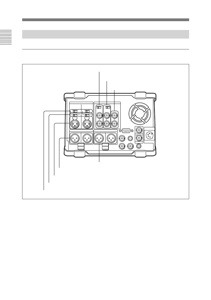
1-3-4 Connector Panel
Analog audio/video input and output section
–60 dBu: Microphone input
0 dBu: Line audio input
+4 dBu: Line audio input
(0 dBu = 0.775 Vrms)
3 AUDIO INPUT CH-1/CH-2
connectors (XLR 3-pin, female)
Input the analog audio signals of input
channels 1 and 2.
1 Phantom power supply switches
2 AUDIO INPUT CH-1/CH-2 level switches
3 AUDIO INPUT CH-1/CH-2 connectors
4 AUDIO OUTPUT CH-1/3 and CH-2/4 connectors
6 REF. VIDEO IN connectors and 75 Ω
termination switch
5 MONITOR OUTPUT L/R connectors
7 VIDEO INPUT connectors and 75 Ω
termination switch
8 VIDEO OUTPUT connectors