2-14
DXC-D30 (UC)
DXC-D30P (CE)
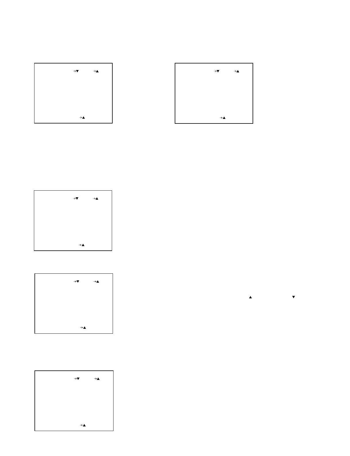
. Page 9 Various kinds items setting 1
FD:
BLKG
READ OUT
20:
MAT DEST SMPTE:
SETUP ON:
PAGE 9 (NEXT PREV )
EXIT MENU (YES )
(for NTSC)
. Page 12 RG, SUB communication
n:This value is changed by each unit. The numerical value is not
changed. According to this, when replacing the TG-175 board or
EEPROM (IC1) on the TG-175 board, the reset is needed. Contact
your authorized Sony dealer.
. Page 10 TEST MODE
B-Y ON:
R-Y ON:
TEST OFF:
PAGE10(NEXT PREV )
EXIT MENU (YES )
HEAD 1 ~ 7 BLOCK No.
HEAD 1 G:
HEAD 6 4:
HEAD 7 6:
HEAD 5 0:
HEAD 4 0:
HEAD 3 0:
HEAD 2 V:
PAGE11(NEXT PREV )
EXIT MENU (YES )
. Page 11 HEAD BLOCK No. information
(for NTSC) Standard value
SETUP ON / OFF of SETUP : ON
READOUT FD reading out
/ FM reading out change : FD
BLKG BLKG width setting
(19/20/21H) : 20
MAT DEST Matrix destination setting
(EBU/SMPTE) : SMPTE
READ OUT FD:
COMP LVL 525:
PAGE 9 (NEXT PREV )
EXIT MENU (YES )
(for PAL)
(for PAL) Standard value
COMP LVL Color differential output
525 / 700 change :525
READOUT FD reading out / FM reading out
change :FD
When replacing the TG-175 board or EEPROM (IC1) on the TG-175 board,
input the BLOCK No. label which is put on the side of the CCD UNIT.
Input method: The BLOCK No. is inputted by UP
switch or DOWN switch.
TEST ON / OFF of TEST SAW
TEST:1 TEST SAW of 100%
TEST:2 TEST SAW of 226%
TEST:3 TEST SAW of 226% at lower side of screen
R-Y ON / OFF of R-Y output
B-Y ON / OFF of B-Y output
R RG 21:
B SUB 78:
TPC +30:
G SUB 85:
R SUB 78:
B RG 21:
G RG 74:
PAGE12(NEXT PREV )
EXIT MENU (YES )


 To Next Page