20
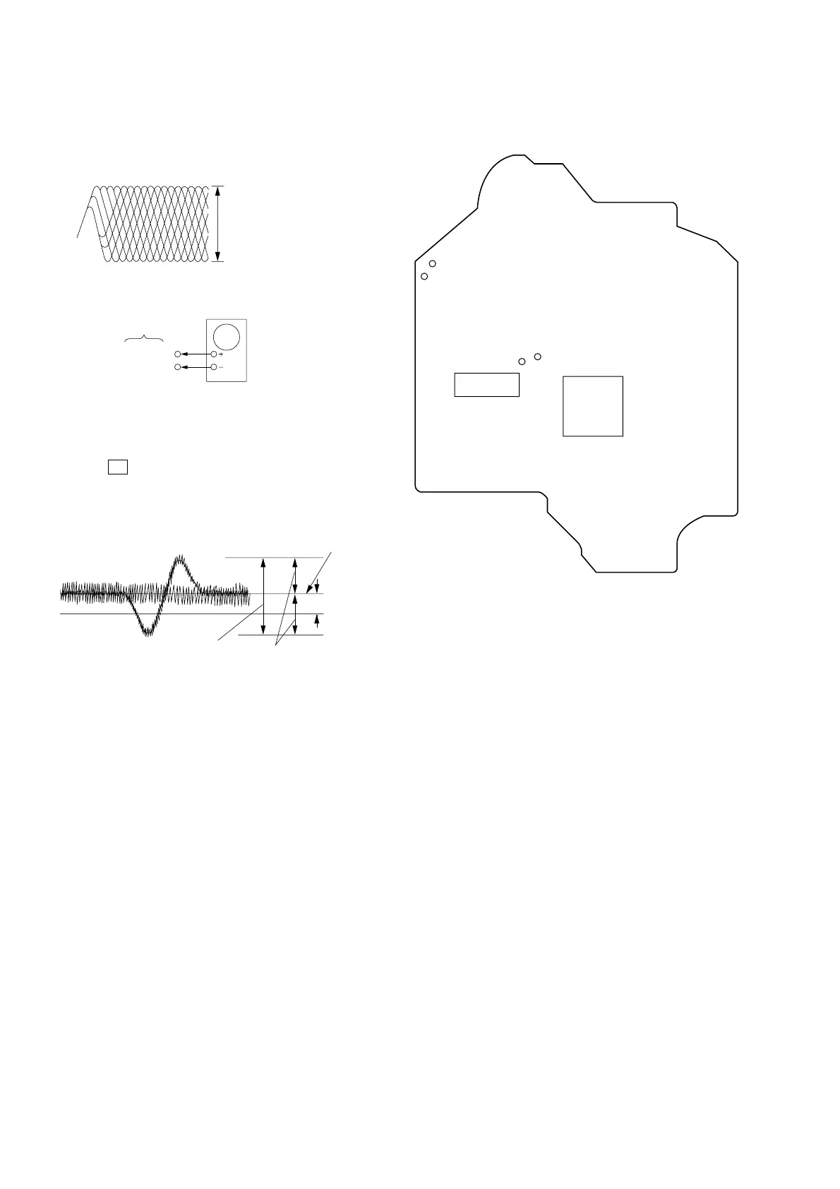
Note : Clear RF signal waveform means that the shape “ ◊ ” can be clearly
distinguished at the center of the waveform.
E-F Balance (1 Track jump) Check
Procedure :
1. Connect oscilloscope to TP (TEO) and TP (VC).
2. Turned Power switch on.
3. Load a disc (YEDS-18) and playback the number five track.
4. Press the X button. (Becomes the 1 track jump mode.)
5. Confirm that the level B and A (DC voltage) on the oscilloscope
waveform.
6. After check, remove the lead wire connected in step 1.
RF signal waveform
VOLT/DIV : 200mV
TIME/DIV : 500ns
level : 1.45 ± 0.3Vp-p
TP(TEO)
TP(VC)
BD board
oscilloscop
level=1.3 ± 0.6Vp-p
symmetry
A (DC voltage
center of
waveform
B
0V
1 track jump waveform
Specified level: –– × 100=less than ±22%
B
A
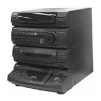
Adjustment Location:
[BD BOARD] (Conductor Side)
TP (RF)
TP (VC)
IC103
IC101
TP (TEO)
TP (FE0)