(E) 3
MJ620
SW1 SW2
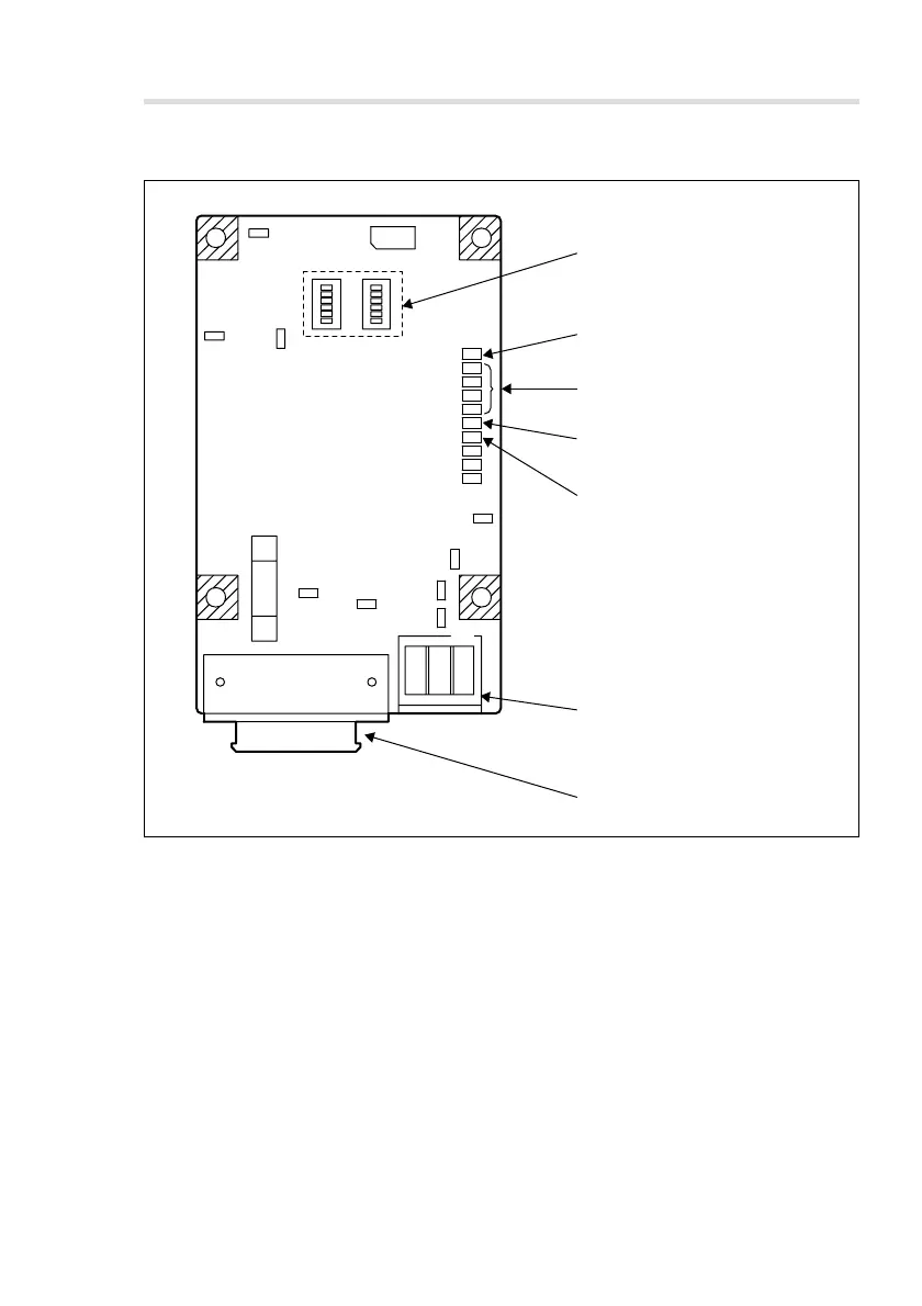
1 MODE switches 1 and 2
(SW1, SW2)
5 (Red) SPEED ALARM lamp
6 Encoder signal input connector
4 (Red) LEVEL ALARM lamp
3 (Green) POS. lamp
2 (Orange) ABS lamp
7 Output connector
3. Operation
3-1. Names of each part
1 MODE switches 1 and 2
The resolution switch, reference point adjustment, etc., determine the functions of the
unit as an interpolator.
2 ABS lamp
Lights when the reference point input signal is active.
3 POS. lamp
Used while setting the reference point.
4 LEVEL ALARM lamp
Lights when the input signal is out of the range allowed by the specifications.