20 (E)
MJ620
Output: A/B
phase,
reference
point signal,
alarm signal,
U/V/W phase
MJ620
+5 V
0 V
50 m or less
Receiver
Twisted pair
(28 AWG or thicker)
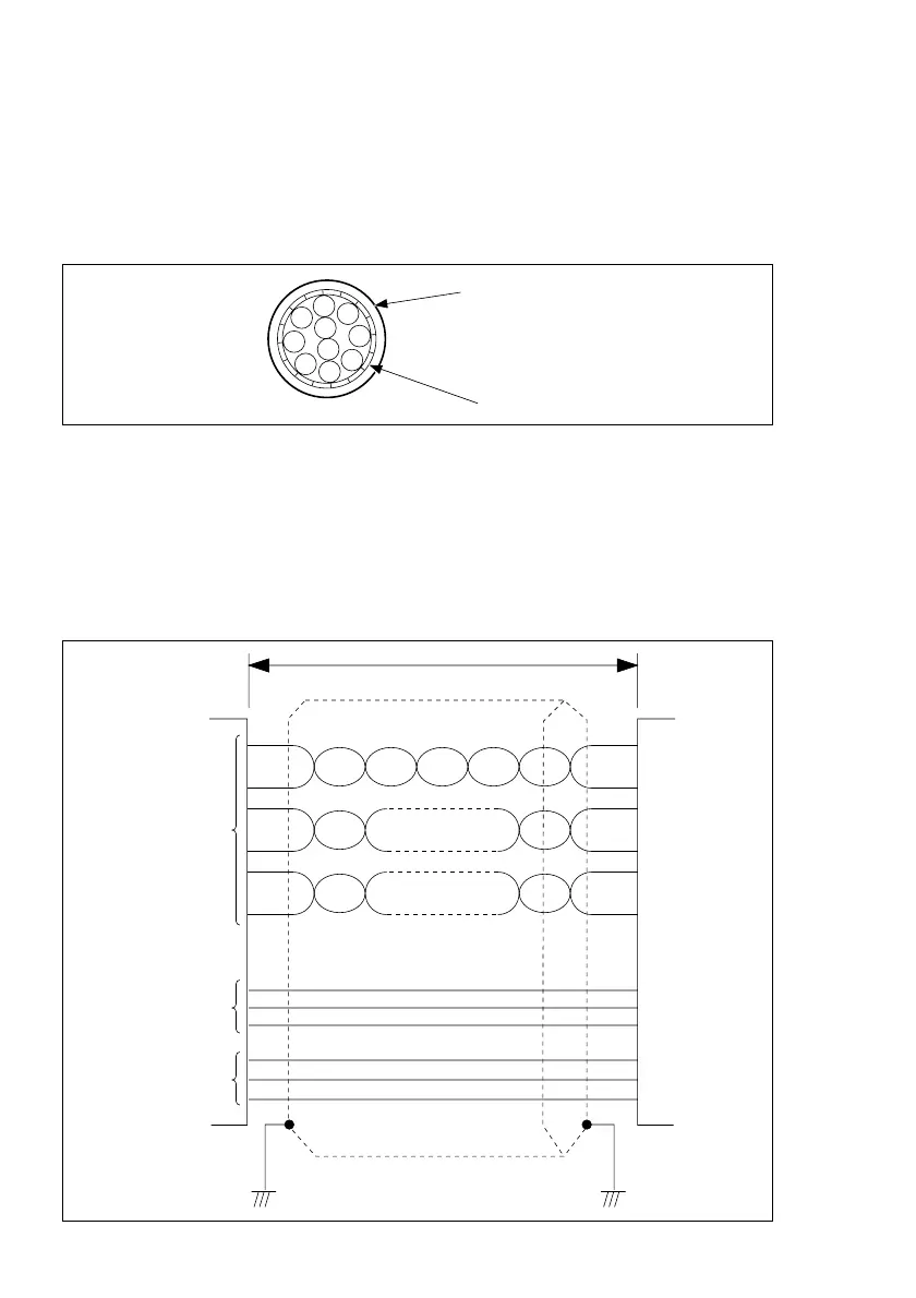
4-2-2. Input and output cable specifications
. Use a shielded cable as shown in the figure below to connect to the output connectors.
. Connect the shielded wires of the cable to the case of each connector.
. Make the cable length as short as possible to prevent noise from entering.
. Use a twisted pair with a thickness of at least 28 AWG for the output cable. The output
signals use voltage-differential line driver output.
. Connect the shielded wires to FG.
. Set the supply voltage so that it satisfies the specified value in the interpolator input unit.
. Recommended cables: 20276-VSV-10P x 26AWG-7/0.16
(Hirakawa Hewtech)
Outer coating
Braided shielding