(E) 9
MJ620
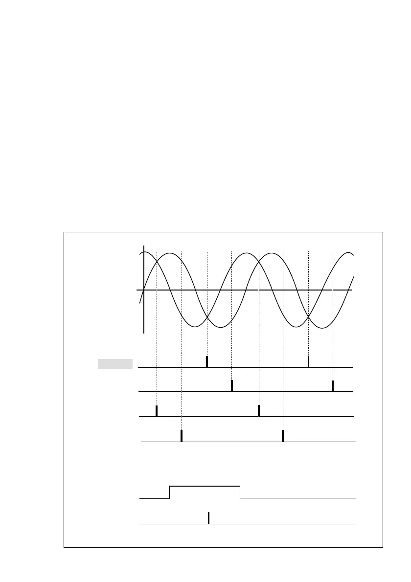
The one-cycle reference point is one of the four
points above and is determined by the
reference point gate logical product.
Reference point
gate signal
Reference point
output
When both mode switches 1-1 and 1-2 are on
COS signal
SIN signal
MODE1
ON ON
OFF ON
Approx. 135
dd
dd
d
ON OFF
Approx. 225
dd
dd
d
Approx. 315
dd
dd
d
OFF OFF
Approx. 45
dd
dd
d
3-4. Using the reference point
In the MJ620, the reference point prerecorded in the encoder can be input from the encoder
signal input connector as an analog reference point gate signal, and the reference point
signals can be output in synchronization with the A/B phase signals.
3-4-1. Principles of reference point output
The MJ620 detect the one-cycle reference points from the SIN and COS signals input from
the encoder. These one-cycle reference points are synchronized with the A/B phase signals
that are output and are located at approximately the 45d, 135d, 225d, and 315d positions as
viewed from the SIN signal of the encoder according to the setting made at mode switches
1-1 and 1-2 (reference point position 1 and 2 switches).