(E) 21
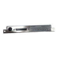
MJ620
PCA, PCB, PCZ, ALARM
PCA, PCB, PCZ, ALARM
****
5. Specifications
5-1. General specifications
Model name MJ620
Number of divisions 800, 400, 160, 80, 40, 32
(number of interpolations)
Minimum phase difference See “3-3-2. Output phase difference.”
Output signal See Fig. 3-1 and 3-2.
Reference point signals Reference point signals are output during one cycle of
the A phase signal (Z mode) or when both the A and B
phase signals are high level (1/4 mode), depending on
the setting.
Output circuit Voltage-differential line driver (AM26C31)
Use the AM26C31 or an equivalent product for the
receiver circuit.
Maximum response speed See “3-6. Maximum response speed.”
Alarm signal See “3-7. Alarm signal.”
Power supply 4.75 to 5.25 V DC
Power consumption 2.2 W (when PL101 Series is connected)
Operating temperature range 0 to +45dC
Storage temperature range _20 to +60dC
Mass 60 g
Accessories Instruction manual.....1
Applicable standards EN55011 Group 1 Class A/91
EN50 082-2/95
FCC Part 15 Subpart B Class A Digital Device
ICES-003 Class A Digital Device