Locations and Functions of Parts and Controls
17
Chapter 1 Overview
When this selector is used with the menu item for
filter selection display set to ON (see page 149),
the new setting appears on the viewfinder screen
for about three seconds.
You can change a MAINTENANCE menu
setting so that different white balance settings can
be stored for different FILTER selector positions.
This allows you to automatically obtain optimum
white balance for the current shooting conditions
in linkage with the filter selection.
For details, see “Adjusting the white balance” on
page 54.
d MENU knob
Changes the page selection or a setting within the
menu.
For details about how to use the MENU knob, see
“Menu Operations” on page 140.
e EARPHONE jack (monaural,
minijack)
You can monitor the E-E
1)
sound during
recording and playback sound during playback.
When an alarm is indicated, you can hear the
alarm sound through the earphone. You can use
this with the EARPHONE jack on the rear of the
unit at the same time. Plugging an earphone into
the jack automatically cuts off the built-in
speaker.
1) E-E: Abbreviation of “Electric-to-Electric”. In E-E
mode, video and audio signals input to the camcorder
are output after passing through internal electric
circuits only. This can be used to check input signals.
f AUTO W/B BAL (automatic white/
black balance adjustment) switch
Activates the automatic white/black balance
adjustment functions.
WHT: Adjusts the white balance automatically.
If the WHITE BAL switch (see page 19) is
set to A or B, the white balance setting is
stored in the corresponding memory. If the
WHITE BAL switch is set to PRST, the
automatic white balance adjustment function
does not operate.
BLK: Adjusts the black set and black balance
automatically.
g MIC (microphone) LEVEL control
Adjusts the input level of audio channels 1, 2, 3
and 4.
For details, see “Adjusting the Audio Level” on page
61.
Right side (near the front)
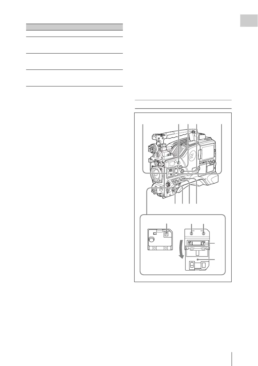
a ASSIGN (assignable) 1/2 switches
You can assign the desired functions to these
switches on the ASSIGNABLE page of the
OPERATION menu.
Nothing is assigned to these switches when the
camcorder is shipped from the factory (equivalent
to a selection of OFF in the menu).
For details, see “Assigning functions to ASSIGN
switches” on page 155.
Position number ND filter
1CLEAR
2
1
/
4
ND (attenuates light to
approximately
1
/
4
)
3
1
/
16
ND (attenuates light to
approximately
1
/
16
)
4
1
/
64
ND (attenuates light to
approximately
1
/
64
)
MENU
ON/
SEL
OFF
STATUS
CANCEL/PRST
ESCAPEON
OFF
6789
qa qs0
qf
qd


 To Next Page