– 45 – – 47 –– 46 –
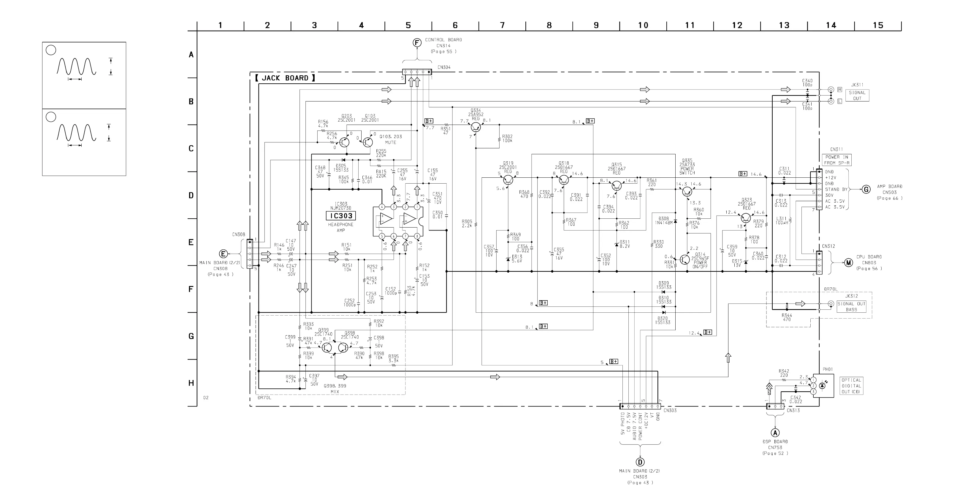
5-7. SCHEMATIC DIAGRAM – MAIN SECTION (3/3) –
PMC-DR50L/DR70L
Note on Schematic Diagram – Main Section (3/3) – :
Note:
• All capacitors are in µF unless otherwise noted. pF: µµF
50 WV or less are not indicated except for electrolytics
and tantalums.
• All resistors are in Ω and
1
/
4
W or less unless otherwise
specified.
• U : B+ Line.
• Voltages are dc with respect to ground under no-signal
(detuned) conditions.
no mark : FM
• Voltages are taken with a VOM (Input impedance 10 MΩ).
Voltage variations may be noted due to normal produc-
tion tolerances.
• Signal path.
F : FM
c : digital out
Note on Schematic Diagram – Main Section (2/3) – :
Note:
• All capacitors are in µF unless otherwise noted. pF: µµF
50 WV or less are not indicated except for electrolytics
and tantalums.
• All resistors are in Ω and
1
/
4
W or less unless otherwise
specified.
• U : B+ Line.
• H : adjustment for repair.
• Voltages and waveforms are dc with respect to ground
under no-signal (detuned) conditions.
no mark : COMMON (REC)
( ) : PLAY
• Voltages are taken with a VOM (Input impedance 10 MΩ).
Voltage variations may be noted due to normal produc-
tion tolerances.
• Waveforms are taken with a oscilloscope.
Voltage variations may be noted due to normal produc-
tion tolerances.
• Circled numbers refer to waveforms.
• Signal path.
F : FM
E : PB
a : REC
J : CD
1
2
L301
Q301 C
ATT : 1/10
VOLT/DIV : 1V AC
TIME/DIV : 5 µsec
VOLT/DIV : 5 V AC
TIME/DIV : 5 µsec
60Vp-
57kHz
15Vp-
57kHz
r
Waveforms – MAIN SECTION (2/3) –



 To Next Page