– 6 –
SECTION 3
DISASSEMBLY
Note : Follow the disassembly procedure in the numerical order given.
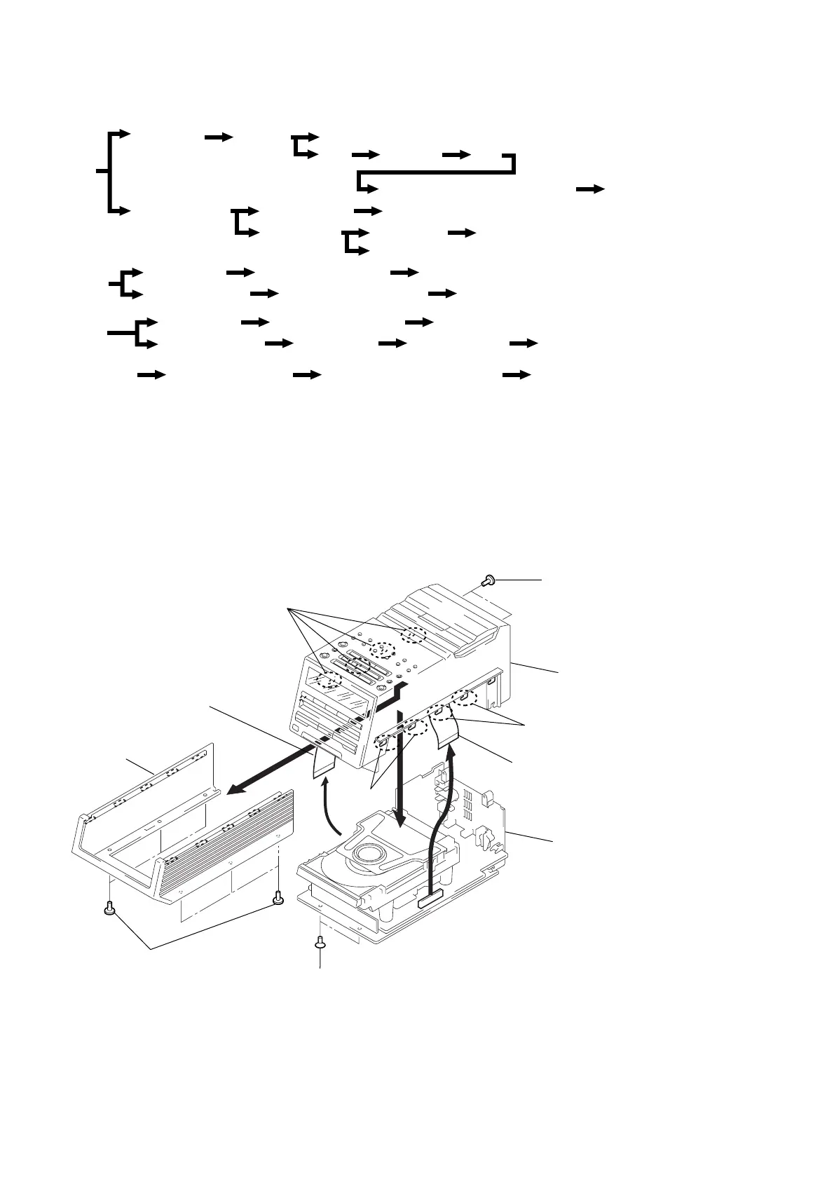
3-1. CASE (BOTTOM) , “COVER ASSY, TOP”
r
The equipment can be removed using the following procedure.
Case(bottom)
Cover ASSY, top
Main unit
CD ASSY Main board, Jack board
Tray ASP board
Motor board, Loading motor (M651) Optical pick-up block
Belt
Mechanism deck TC RF board, Head relay board, Capstan/reel motor (M160)
Control board
VOL board
Display board
Cabinet, wood
Speaker unit
(R-CH)
Speaker (R-CH) (SP101) Power board
Cabinet (R) bottom
Speaker board
AMP board, AMP IC board
Cabinet, wood
Speaker unit
(L-CH) (DR70L)
Speaker (L-CH) (SP201) Power transfomer board
Super woofer unit
(DR70L)
Speaker (SP601), “Cabinet, front”
Cabinet (SWF) bottom LED board, volume board
Cabinet (L) bottom SP main board
AC outlet board, SP jack board
SP AMP IC board
DSP board, CPU board
5
Wire, parallel (19 core)
6
Wire, parallel (20 core)
(ASP board : CN702)
1
Screws (+BVTT 3x10)
1
Screws (+BVTT 3x10)
4
Screws (+KPT 3x10)
3
7
Case (bottom)
Sub cover
2
Claws
2
Claws
2
Claws
Cover ASSY, top
< MAIN UNIT >
 Loading...