HT-S500RF/S700RF
12
Sony CONFIDENTIAL
For Authorized Servicer
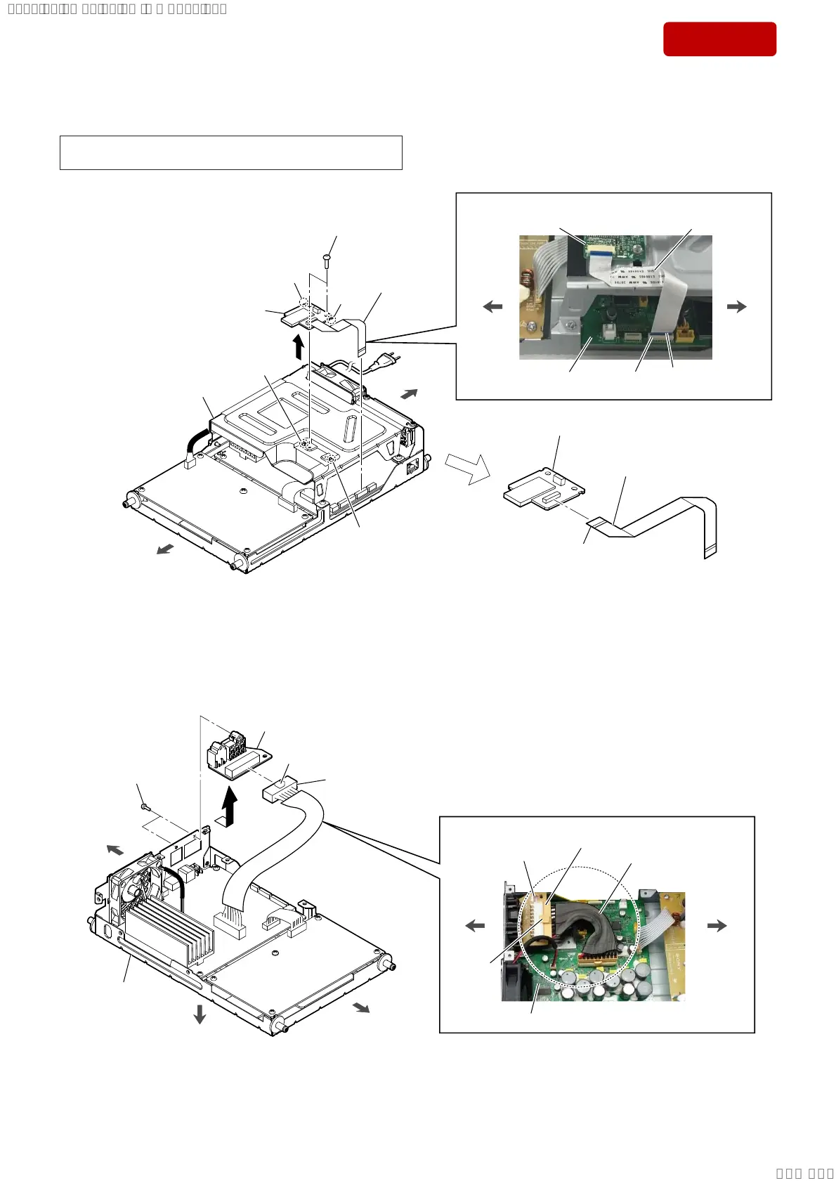
2-5. BT BOARD
1 FFC (BT)
(24 core)
(XP2)
AMP block
3
5 FFC (BT) (24 core)
(XP10)
front side
2 two screws
(BVTT3 u 6)
groove
4 BT board block
Note 2:
When installing the BT board
block, align the two ribs and
two grooves.
groove
rib
rib
6 BT board
(See Note 1)
))&%7FRUHVHWWLQJ
–6LGHYLHZ–
The opposite side
is terminal side.
BT board
FFC (BT)
(24 core)
XP2
MAIN board
front side
rear side
rear side
terminal side
2-6. SPK JACK BOARD
1 cable (MAIN SPK JACK) (10 pin)
connector (XP6)
2 two screws
(BVTP3 u 10)
3
4 SPK JACK board
AMP block
front side
rear side
bottom side
:LUHVHWWLQJ
cable (MAIN SPK JACK)
(10 pin)
–7RSYLHZ–
rear side
front side
XP6
SPK JACK board
MAIN board
claw side
claw side
Note 1: When the BT board is replaced, refer to “OPERATION CHECK
OF THE BLUETOOTH CONNECTION” on page 7.
SYSSET
2018/11/2806:27:54(GMT+09:00)