HT-S500RF/S700RF
8
Sony CONFIDENTIAL
For Authorized Servicer
SECTION 2
DISASSEMBLY
• This set can be disassembled in the order shown below.
2-1. DISASSEMBLY FLOW
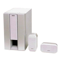
SET (SA-WS500RF/WS700RF)
2-5. BT BOARD
(Page 12)
2-12. SERVICE POSITION
(Page 18)
2-2. CATCHER RUBBER (REAR SIDE),
REAR PANEL
(Page 9)
2-4. TOP CHASSIS BLOCK,
POWER CORD
(Page 11)
2-10. FL BOARD, SW PANEL,
LED WINDOW W TOUCH
(Page 16)
2-3. AMP BLOCK,
CATCHER RUBBER (FRONT SIDE)
(Page 10)
2-6. SPK JACK BOARD
(Page 12)
2-9. FRONT PANEL BLOCK
(Page 15)
2-7. MAIN BOARD
(Page 13)
2-8. POWER BOARD
(Page 14)
2-11. SW UNIT (SUBWOOFER)
(Page 17)
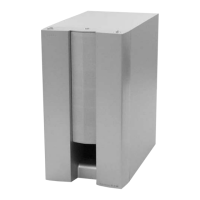
JIG
When disassembling the unit, use the following
jig for speaker removal.
Part No. Description
J-2501-238-A JIG FOR SPEAKER REMOVAL
Note:
SA-WS500RF and SA-WS700RF can be removed using
the same procedure.
This explanation uses illustrations from the SA-WS500RF.
SYSSET
2018/11/2806:27:54(GMT+09:00)