HT-S500RF/S700RF
13
Sony CONFIDENTIAL
For Authorized Servicer
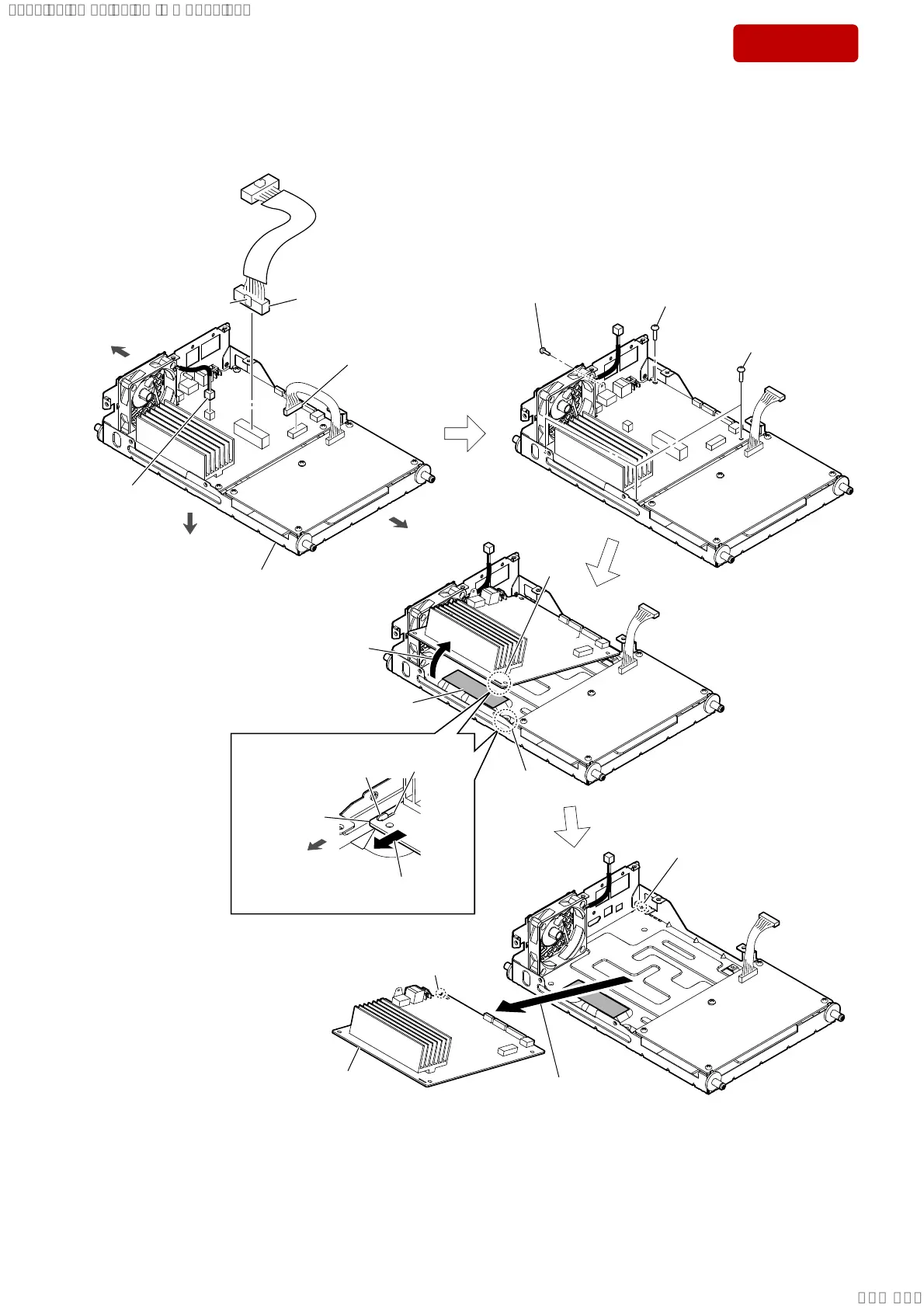
2-7. MAIN BOARD
5 three screws
(BVTT3 u 6)
5 screw
(BVTT3 u 6)
3 POWER board cable
connector (XP1)
AMP block
front side
rear side
bottom side
1 cable (MAIN SPK JACK) (10 pin)
connector (XP10)
2 fan cable
connector
(XP8)
claw side
4 screw
(BVTP3 u 10)
heat radiation sheet
hole
groove
rib
MAIN board
front side
9 Remove the MAIN board
in the direction of the arrow.
8
Lift up the MAIN board
in
the direction of the arrow.
6 Slide the MAIN board in the direction
of the arrow, and remove the rib.
hole
rib
7
rib
0 MAIN board
Note:
When installing the MAIN board,
align the rib and groove.
– Inner view –
SYSSET
2018/11/2806:27:54(GMT+09:00)