12
(GB)
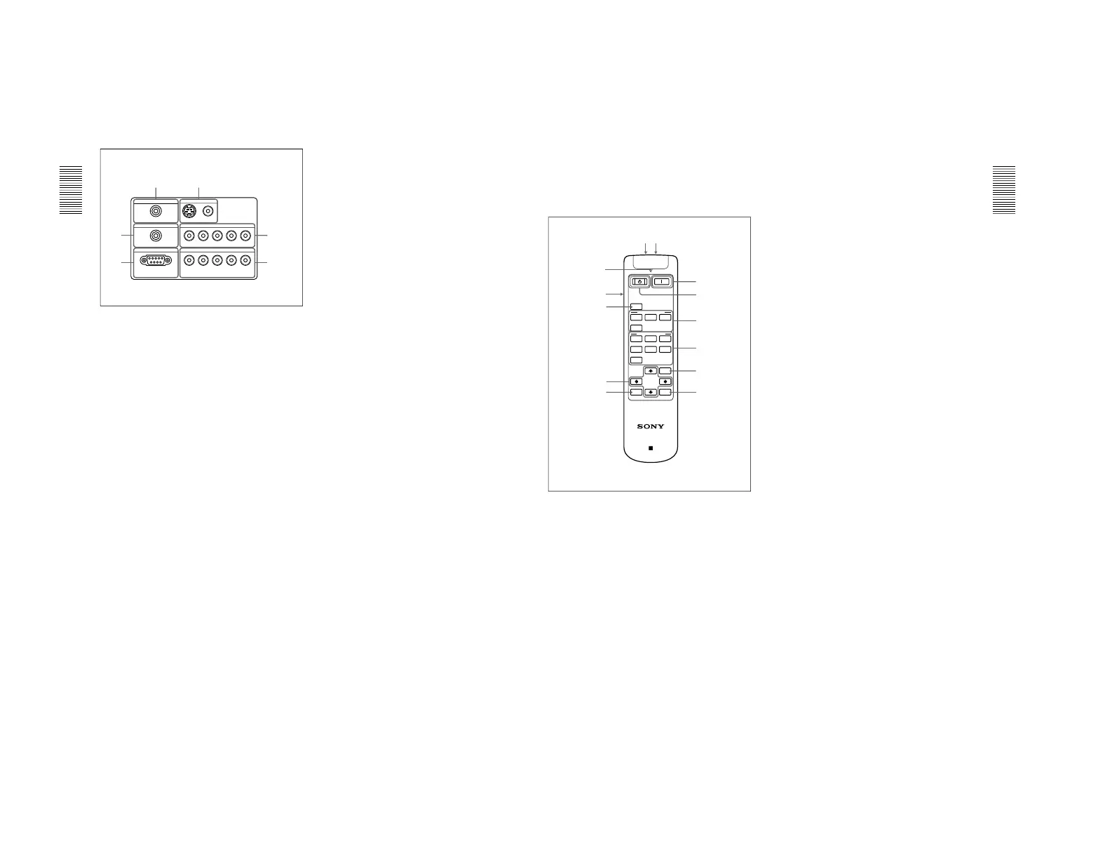
Connector panel
1 INPUT A connectors
G/Y, B/C
B
/P
B
, R/C
R
/P
R
, SYNC/HD, VD connectors
(phono type):
Connect to the RGB output of the equipment.
According to the connected equipment, computer,
component (Y/C
B
/C
R
), HDTV or DTV (DTV GBR,
DTV YP
B
P
R
) signal is selected.
2 INPUT B connectors
G/Y, B/C
B
/P
B
, R/C
R
/P
R
, SYNC/HD, VD connectors
(phono type):
Connect to the RGB output of the equipment.
According to the connected equipment, computer,
component (Y/C
B
/C
R
), HDTV or DTV (DTV GBR,
DTV YP
B
P
R
) signal is selected.
3 RS-232C connector (D-sub 9-pin, female)
This is a service connector.
4 TRIGGER connector (minijack)
Outputs the ON or OFF condition of the unit to the
external equipment.
When the unit is turned off, 0 V is output and when
the unit is turned on, 12 V is output. However, as
power is not output, you cannot use the connector as a
power source.
5 CONTROL S IN/PLUG IN POWER (DC 5V
output) jack
Connects to the control S out jacks of the Sony equipment.
Connects to the CONTROL S OUT jack on the supplied
Remote Commander when using it as a wired Remote
Commander. In this case, you do not need to install the
batteries in the Remote Commander, since power is
supplied from this jack.
If this connector is used, the Remote Commander key
lamp is not turned on.
Left side
Location and Function of Controls
13
(GB)
Remote Commander
The keys which have the same names as on the
control panel function identically.
You can control a connected computer using the
Remote Commander.
For details, see “Connecting with a Computer” on page
16 (GB).
1
I
(ON) key
Press this key to turn on the projector. (It is assumed
that the projector is in the Stand-by state.)
2
1
(OFF) key
Press this key to turn off the power immediately.
3 INPUT SELECT keys
Select the input signal.
VIDEO: Selects the signal of equipment connected
to the projector’s VIDEO connector.
S VIDEO: Selects the signal of equipment
connected to the projector’s S VIDEO connector.
A: Selects the video signal of equipment connected
to the INPUT A connectors.
B: Selects the video signal of equipment connected
to the INPUT B connectors.
Location and Function of Controls
4 VIDEO MEMORY keys
You can store an image setting to one of the VIDEO
MEMORY keys (1 – 6), and you can directly recall
the setting by pressing the appropriate key.
For more details on how to set the video memory, see the
VIDEO MEMORY of the INPUT SETTING menu on page
25 (GB).
5 MENU key
6 ENTER key
7 RESET key
8 Arrow keys (M/m/</,)
9 MUTING PIC key
Cuts off the picture. Press again to restore the picture.
0 LIGHT switch
Pressing this switch turns on the key light on the
Remote Commander. Pressing this switch again turns
off the key light. If no keys are operated, the lights
will automatically turn off in 30 seconds.
Install the two batteries in the Remote Commander
when you use the key light.
qa Transmission indicator
Lights up when you press a key on the Remote
Commander.
qs CONTROL S OUT jack (stereo minijack)
Connects to the CONTROL S IN jack on the projector
with the connecting cable (not supplied) when using
the Remote Commander as a wired one. In this case,
you do not need to install the batteries since the power
is supplied via the CONTROL S IN jack on the
projector.
If the batteries are not installed, the Remote
Commander key light is not turned on.
qd Infrared transmitter
 Loading...