58 Service manual
3. Circuit Boards - CCD Sensor / Filter CRANEX
®
Novus e
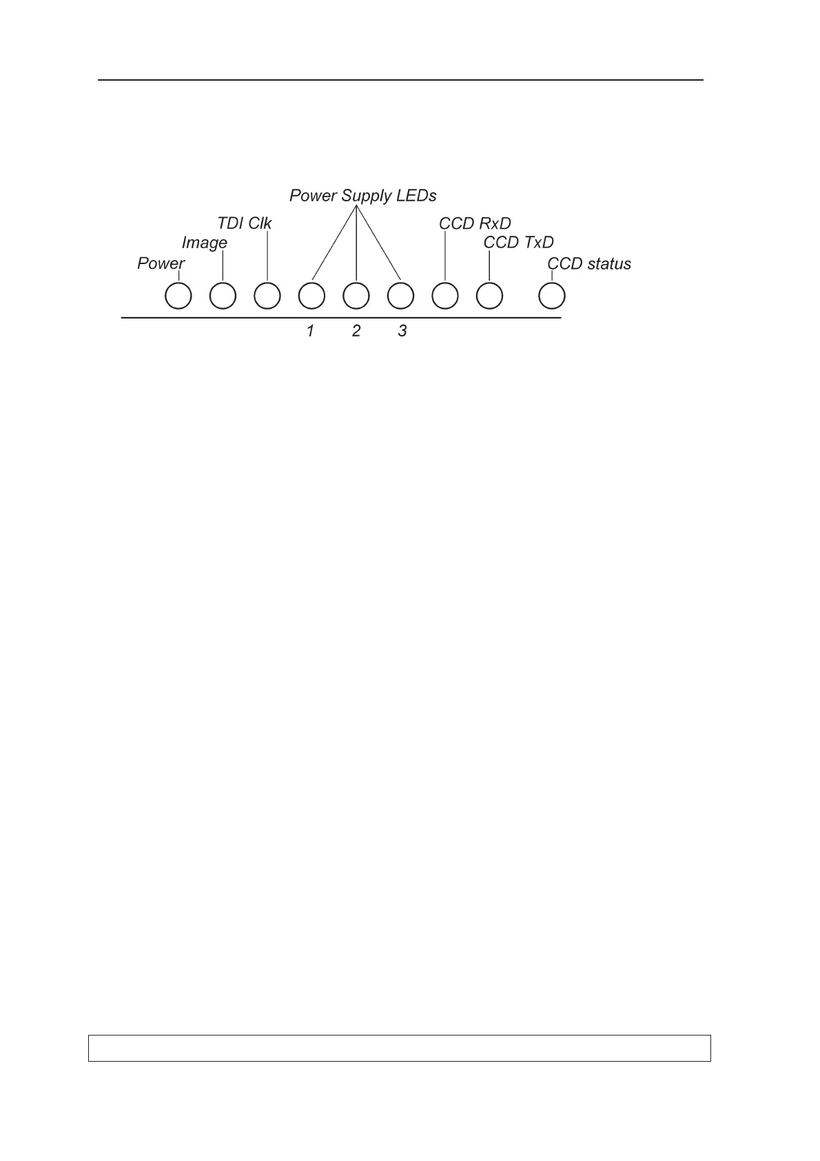
CCD - Indicator lights
Remove the covers from the CCD side of the rotating
unit On the rear of the CCD sensor there are a number
of LEDs that indicate the status of the CCD sensor.
LED Colour Indicates
Power Yellow Indicates that the power signal is active.
Image Yellow Indicates image signal activity. It tells the CCD sensor
A/D-converter to sample image data according to the
TDI frequency.
TDI Clk Yellow Indicates that the clocking frequency of the CCD is
available.
Off TDI frequency is between 0...50Hz.
On TDI frequency is between 100 Hz...1kHz.
Flashing TDI frequency is between 50...100Hz or above 1kHz.
Power Supply Indicate the different voltages required by the CCD
sensor. The microcontroller in the CCD sensor monitors
the voltages and activates the LEDs accordingly.
There are software set limits for the various supply
voltages. The LEDs come on during image capture.
1 Yellow +3.3V and +1.8V LEDs
Supply voltages for the CCD clock controlling FPGA.
The +3.3V is generated by L1500.
The +1.8V step down is generated in CCD sensor
board from +3.3V.
LIMITS:
+3.3V between +3.0 and +3.6V.
+1.8V between +1.71V and +1.89V.
2 Yellow Analog +5V LED.
Supply voltage for AD-converters.
LIMITS:
between +4.5V and +5.5V