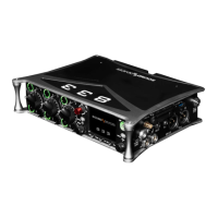
Tips: When CL-12 is connected to the 833 trim gains are controlled from the 833.
Slate mic can be toggled on/off by pressing both COM 1 and COM 2 simultaneously.
When adjusting EQ from the CL-12, the EQ values are displayed at the bottom of the 833 meter view.
A USB-A to USB-A cable is required to connect the CL-12.
Pressing stop while in stop will toggle between editing the next take and current take’s scene, take and notes metadata.
Third Party Controllers
1. Require Shift for Arm: When selected, “Shift” on external control surface must be pressed simultaneously with “Rec” to
arm tracks. [Off*, On]. Applies to supported 3rd party controllers only.
2. Require Shift for Mute: When selected, “Shift” on external control surface must be pressed simultaneously with “Mute” to
mute channels, buses, and outputs. Applies to supported 3rd party controllers only.
3. Solo Follows Select: Selects whether solo (PFL) mode is engaged on a channel when pressing “Select” from the controller
[Off, On*]. Applies to supported 3rd party controllers only.
4. Main Fader: Sets which bus or output a third party controller’s main fader controls.
5. Multiple Controllers: When multiple controllers are simultaneously connected to the 833 via a USB hub, sets whether they
operate in Spill or Individual mode.
a. SPILL: In Spill Mode, all MCU controllers connected to the 833 work as one big control surface. All controllers
operate in the same mode (e.g. Mix Mode, Bus Mode, Output Mode etc), all channel strips join into a single
fader bank spilled across all controllers, and all controlled parameters spill across all available channel strips.
For example, with the +4 plugin installed, a setup with two 8-fader controllers spills faders 1-8 to controller 1 and
faders 9-12 to controller 2. The USB Hub port number determines which controller is Controller 1 and which is
Controller 2. Controller 1 must be connected to a lower USB port number than Controller 2. On most hubs, the
USB port numbering is not marked in which case, try the various ports to determine the hub’s USB port
numbering.
b. INDIVIDUAL: In Individual Mode, each controller behaves independently with its own operating mode and fader
bank. For example, this allows using one controller for the main channel mix in Mix Mode and a separate
controller for setting up IFB feeds in Bus Mode or Bus Sends on Faders Mode. A third controller could be used
for output control in Output mode.
Control Modes
A Control Mode determines the function of a controller’s faders, VPots, and other buttons.
The VPots are the multi-function encoder knobs positioned above each channel’s fader.
Mix Trim Mode (Home). For mixing channels to the main LR bus. Switches faders to channel faders and VPots to channel trims.
Mutes and Solos buttons are channel mutes and solos respectively.
Fat Channel Mode. For editing various channel parameters including Trim, Pan, Source, Delay, Phase, Limiter, HPF, EQ, and Bus
Sends.

 Loading...