Verify that the current model displayed on this screen is the model you wish to copy. If not then see
page 14 Model Select to access the desired model. Rotate the roller to select the model memory (1 -
30) that the model will be copied to. Select an unused model memory to copy to. When the desired
model memory is displayed, press the roller to access the Confirm Copy screen.
Confirm Copy IM™ From 1 MdlOIHeli To £
Mdl02-Acro
□ATA WILL EE OVERWRITTEN CANCEL I COPY l
If you want to Copy this model to the selected model memory, press the roller to copy. The
screen returns to the main screen when the copy is complete. The original model memory you
just copied will still be selected.
TELEMETR To Bind the Telemetry Module and Receiver
1.Press and hold the bind button on the side of the TM1000
Y
Spektrum's TM1000 telemetry module is compatible with all Spektrum and JR receivers that
have a Data (Flight Log) port including: telemetry module. 2.While depressing the bind button,
power the
receiver. The main receiver, all attached
•AR9000
•AR9200
•AR9300
•AR7100
•AR9100
Binding
•R1221 •R1222
WARNINGS
The Warnings function programs an alarm to sound if specific switches or stick positions are in
an unsafe position when the transmitter is first turned on. In helicopter model type default
warnings include Throttle, Stunt 1, Stunt 2 and Hold. In airplane model type these warnings
include Throttle Low, Flaps, Gear, Flight Mode 1 and Flight Mode 2. If you turn the transmitter on
and any of these switches or the throttle is not at the low position, the alarm will sound; the
screen will display the warning and no transmission will occur until the stick or switch is in the
correct position.
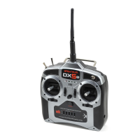
To Access the Warnings Screen
Press and hold the roller while turning on the transmitter. When System Setup appears on the
screen, release the roller. The DX8 is now in System Setup Mode.
Rotate the roller to highlight Warning then press. The
following screen appears:
IWESi
Uarnings
Throttle: Over 10K Stunt
1: Act Stunt 2: Act Hold:
Act Al Tone/*
Highlight the desired warning (Throttle, Stunt 1, Stunt 2 or Hold or Throttle, Flaps, Gear, Flight
Mode 1 and Flight Mode 2 for airplane model) then press the roller to select. Now rotate the
roller to inhibit or activate the selected warning. To verify the warning is functioning turn the
transmitter off, move the selected switch or throttle in the offending position then turn the
transmitter on. The alarm will sound; the screen will display the specific warning and no
modulation will occur.
Warnings EH
Throttle: Over \~\Qi i Stunt 1: Act Stunt £: Act Hold: Act A1 ~ni:
Tone/*
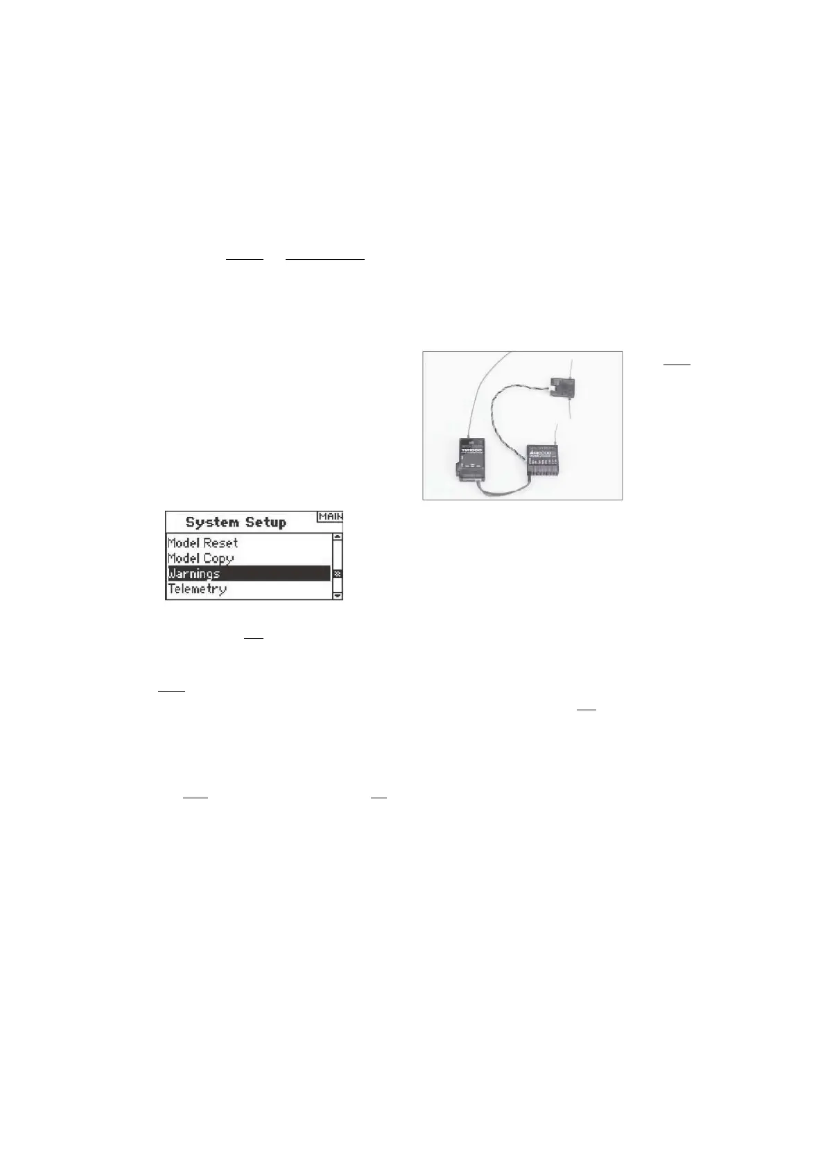
Installing the TM1000
Mount the TM1000 module near
the receiver in a position that
allows the 3-inch data lead to
extend from the receiver's Data
port to the Data port on the
telemetry module. You can use
servo tape to secure the
TM1000 module or wrap it in
foam with the receiver. Plug the
Data lead into the TM1000 port
marked DATA and plug the
other end of the lead into the
receiver's DATA port.
NOTICE: Route and secure the antenna away from any metallic or conductive materials to give
the best range.
At this point the internal telemetry including the flight log data and the receiver pack voltage is
fully functional.
Before continuing, bind the system to the transmitter and confirm the telemetry system is
functioning.
remote receivers and the TM1000 telemetry module will blink indicating the system is in
bind mode.
3.With the stick and switches in the desired failsafe positions (normally low throttle and neutral
sticks), put the transmitter into
bind mode.
TWEii
4. The main screen displays the receiver type. After several seconds, the system
connects and reverts to the main screen.
bind nai
Model 13: Mdl13-Acro
Binding
2048/11ms

 Loading...