KGE/EN (1711) 6.5 Installation and preparation start-up 19
KGE
3.4 Piping accessories
• A foot valve in the suction line is not required for this selfpriming pump.
• Foreign particles can damage the pump. Avoid the entry of big or hard particles by
installing a strainer.
3.5 Foundation / base plate
• The foundation must be hard, level and flat.
• To anchor the base plate, proceed as follows :
3.5.1 Pump units assembled on base plate
The following applies when the units are assembled on the base plate:
• A coupling guard protecting from rotating parts must always be installed.
• The pump and motor shafts of complete units have been accurately factory-aligned.
After arrangement of the pump unit, check the pump and motor shaft alignment and, if
necessary, realign as follows:
The KGEF close coupled pump can be fastened directly on a foundation; realignment is
not necessary.
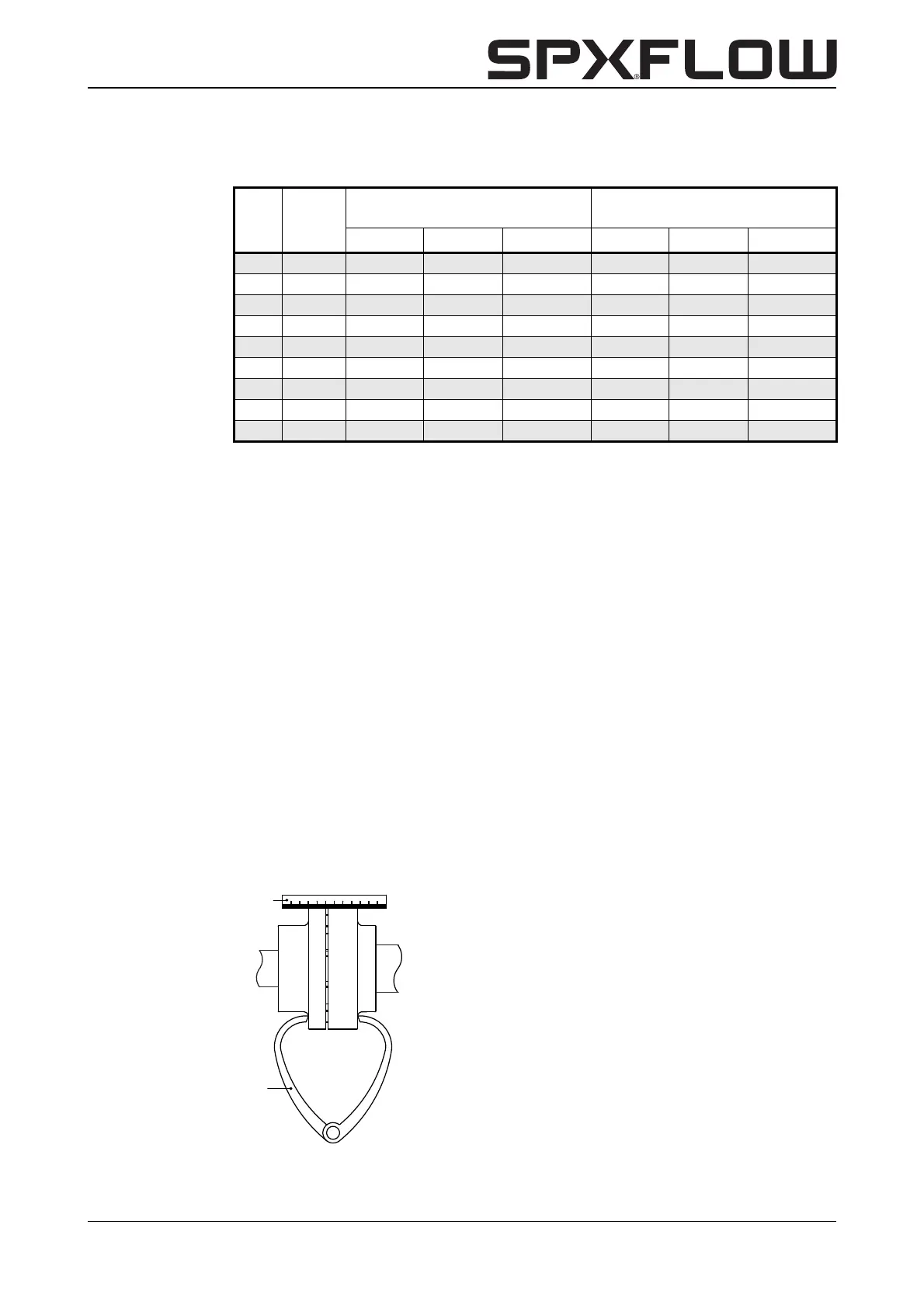
3.5.2 Alignment pump unit
Place a ruler (A) on the coupling; the ruler should touch both half couplings over the
entire length (see figure 4).
Table 1: Permitted forces and torques on the flanges (based on ISO5199)
KGE bracket
Pump or base plate not set in
concrete
Pump or base plate set in
concrete
Fv
max.
[N] Fh
max.
[N] M
max.
[Nm] Fv
max.
[N] Fh
max.
[N] M
max.
[Nm]
11-3 0 1060 950 175 1900 1500 450
11-4 0 1060 950 150 1900 1500 425
16-3 0 1230 1050 250 2150 1800 625
12b-5 0 1230 1050 250 2150 1800 625
12-5 0 1230 1050 250 2150 1800 625
12-6 0 1570 1250 475 2750 2500 1200
15-6 0+ 1270 1050 325 2350 2100 850
16-6 0+ 1270 1050 325 2350 2100 850
14-8 0+ 1400 1050 400 2550 2300 1000
Figure 4: Aligning the coupling by means of a ruler and a pair of outside calipers.