Waukesha Cherry-Burrell Installation
10/2012 95-03087 Page 13
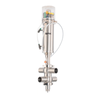
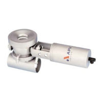
6. Connect the electrical control cord to the valve at location A
(see Figure 3).
NOTE: Co
ntrol tops are available with strain relief cord grip for
hard wiring or threaded pin connectors for quick disconnect.
Mating cables must be ordered separately.
7. Operate the valve through the four conditions (closed, open,
upper seat cleaning and lower seat cleaning). See “Solenoid/
Valve Position” on page 16.
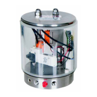
Quality of Control Air to
Control Module
Do not exceed the following values:
• Suspended solids content:
Particle size: 5 microns max.
Particle Density: 5 mg/m
3
max. (= quality class 3)
• Water content: Dewpoint +35
°F (+1.6°C)
(= quality class 3). For applications at great elevations or at
low ambient temperatures, the dewpoint changes.
• Oil content (if possible, without oil): Up to 25mg/m
3
max. oil
(= quality class 5).
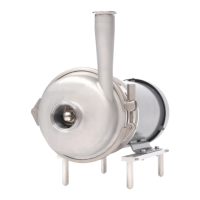
External Flush - Liquid
Vent Cavity
NOTE: Liquid flush of the vent cavity is
typically used in applications with high
sugar content product that may
crystallize if dried. Cavity flush is
recommended after valve transitions to
keep the seats and cavity moist.
Figure 4 - Upper Stem Flush Adapter
Figure 5 - Lower Stem Flush Adapter
Liquid Vent Cavity Only
Use Upper Stem Flush Adapter
Liquid Vent Cavity and Lower Stem
Use both Upper Stem Flush Adapter and Lower Stem Flush/
Steam Adapter.
Options allow for the liquid flush of the vent cavity and leakage
channel alone or with the lower stem flush.
Figure 3 - Control Top Wire Connection
Point
VA100-724
A