Operation Waukesha Cherry-Burrell
Page 16 95-03087 10/2012
Operation
All functions of W-Series mix proof valves are pneumatically con-
trolled using a 75 min. to 100 max. psi (5.2 to 6.9 bar) clean air
supply.
The valve contains a large and small spring in the valve actuator.
The springs hold the valve seats in the closed position.
Large Spring
• Located in top air chamber of cylinder.
• Holds valve in the closed position.
Small Spring
• Located in the extended hub of the upper piston.
• When the valve is open, the spring acts on the upper seat
stem to hold the upper and lower plugs together.
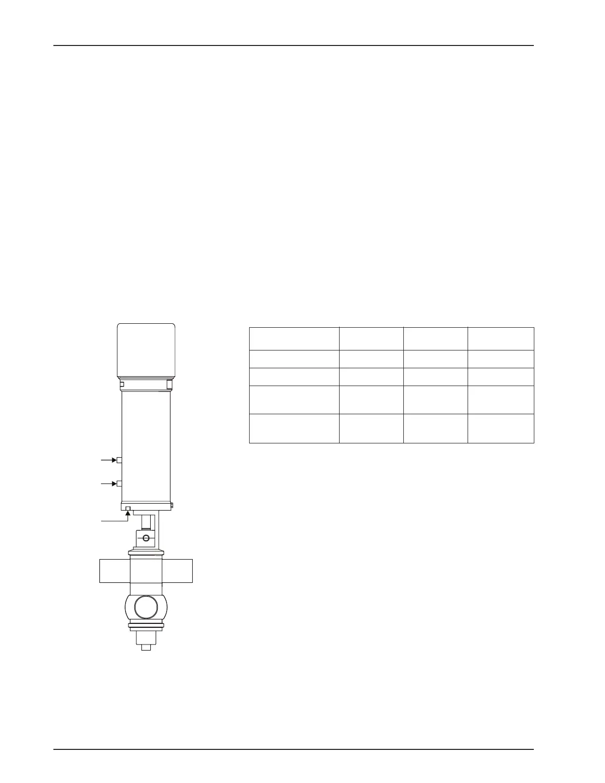
Solenoid Valve Port
Connections
Figure 9 - Solenoid Valve Port
Connections
VA100-093E
Up to three air supplies controlled by solenoid valves supply air to
the valve actuator (Figure 9).
Table 3: Solenoid/Valve Position
Condition Solenoid 1 Solenoid 2 Solenoid 3
Closed OFF OFF OFF
Open ON OFF OFF
Upper Seat
Cleaning *
OFF ON OFF
Lower Seat
Cleaning *
OFF OFF ON
1 = Valve Open Inlet Solenoid
2 = Upper Seat Clean Inlet Solenoid*
3 = Lower Seat Clean Inlet Solenoid*
ON = Solenoid energized (OPEN). LED is lit.
OFF = Solenoid de-energized (CLOSED). LED is off.
Solenoids are normally closed.
Air connections are 1/8" NPT x 1/4" push-to-connect poly tube fit-
tings.
* Seat lifting is an option which requires (2) two additional air sup-
plies. Non-seat lifting valves (NSL) only have one air inlet (1).
For specific air-routing and solenoid porting, please refer to con-
trol module publications 95-03083 (2-piece) or 95-03077 (3-Piece
(obsoleted)).