Operation Waukesha Cherry-Burrell
Page 18 95-03087 10/2012
6. Vent the air in chamber 2 (Figure 9, page 16) to deactivate
the seat lift.
7. If used, pressurize chamber 3 to activate the lower seat push.
8. Confirm that the proximity
switches conform to Table 4 on
page 17. Verify the switch status on the PLC control system.
9. Vent the air in chamber A to deactivate the seat lift.
10. Disconnect the air from the valv
e actuator. placing the valve
in the fail-safe position. Verify that the proximity switches reg-
ister that the valve is fully closed.
Corrective Action
If the double seat Mix Proof valve fails to respond as indicated
above, immediately check the valve assembly and wiring to
locate and correct the cause:
• First, check the proximity switch adjustment.
• Check for the correct assembly and adjustment of the valve.
• For specific information on switch setting, please refer to
control module publications 95-03083 (2-piece) or 95-03077
(3-Piece (obsoleted)).
Valve Operating
Conditions
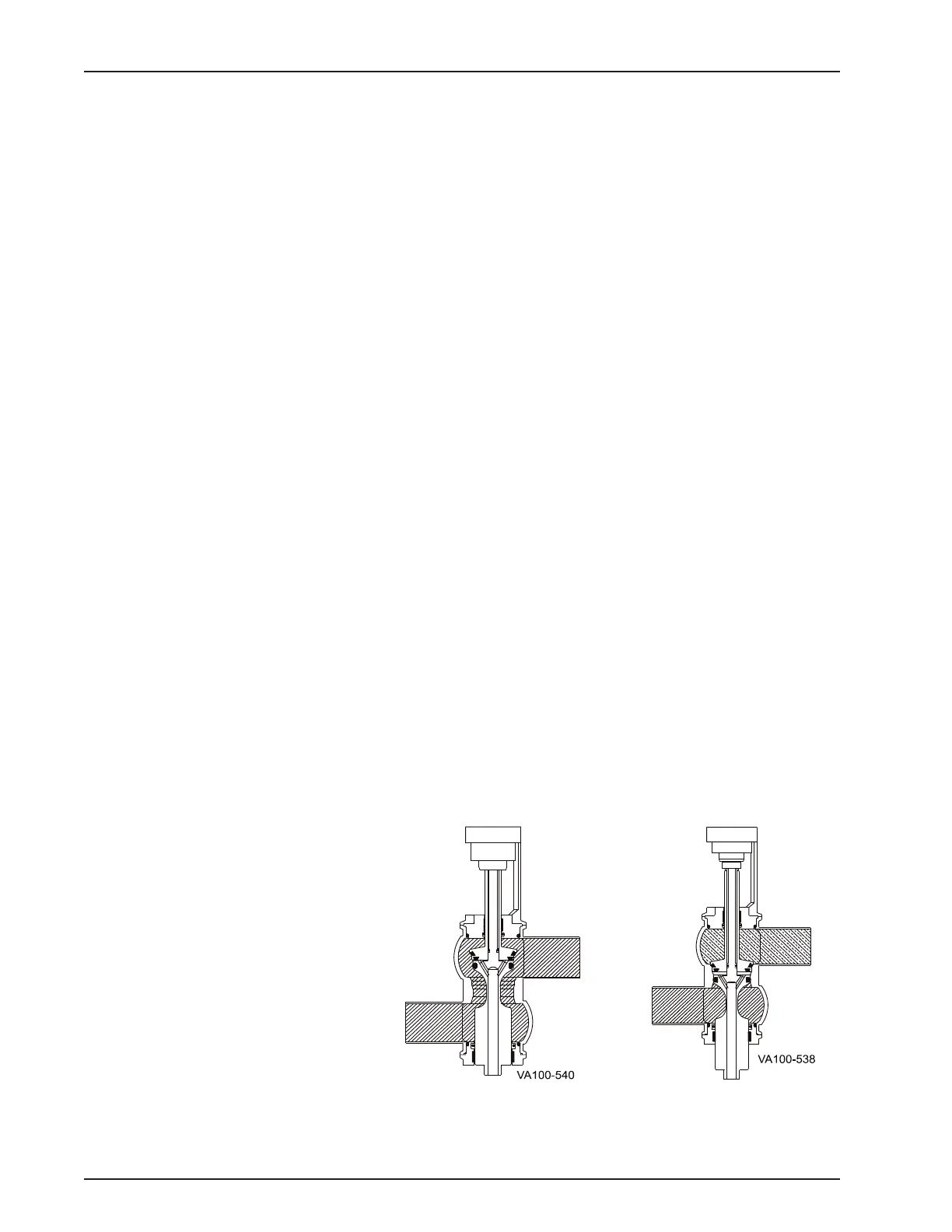
See Figure 9 on page 16 for port and corresponding chambers.
Valve Open
The valve is open when Chamber 1 is pressurized and Chambers
3 and 2 are vented. See Figure 10.
Valve Closed
The valve is closed when Chambers 3, 1, and 2 are vented. The
large spring closes the valve to the fail safe position. See Figure
11.
Figure 10 - Valve Open Figure 11 - Valve Closed