Maintenance Waukesha Cherry-Burrell
Page 28 95-03087 10/2012
Actuator O-ring and
Bearing Replacement
CAUTION: The valve stems and actuator must be
removed from the valve body before servicing the actuator
components.
NOTE: Do not pressurize the actuator with air when the stems
are removed. This may tear the o-rings and cause the actuator to
leak air when it is re-assembled.
Removal of O-rings and Bearings, Non-Seat Lifting
Actuators
NOTE: If present, the control module must be removed to replace
the o-rings and bearings in the top of the cylinder assembly.
Pleaserefer to control module publications 95-03083 (2-piece) or
95-03077 (3-Piece (obsoleted)).
Non Seat Lifting Actuators
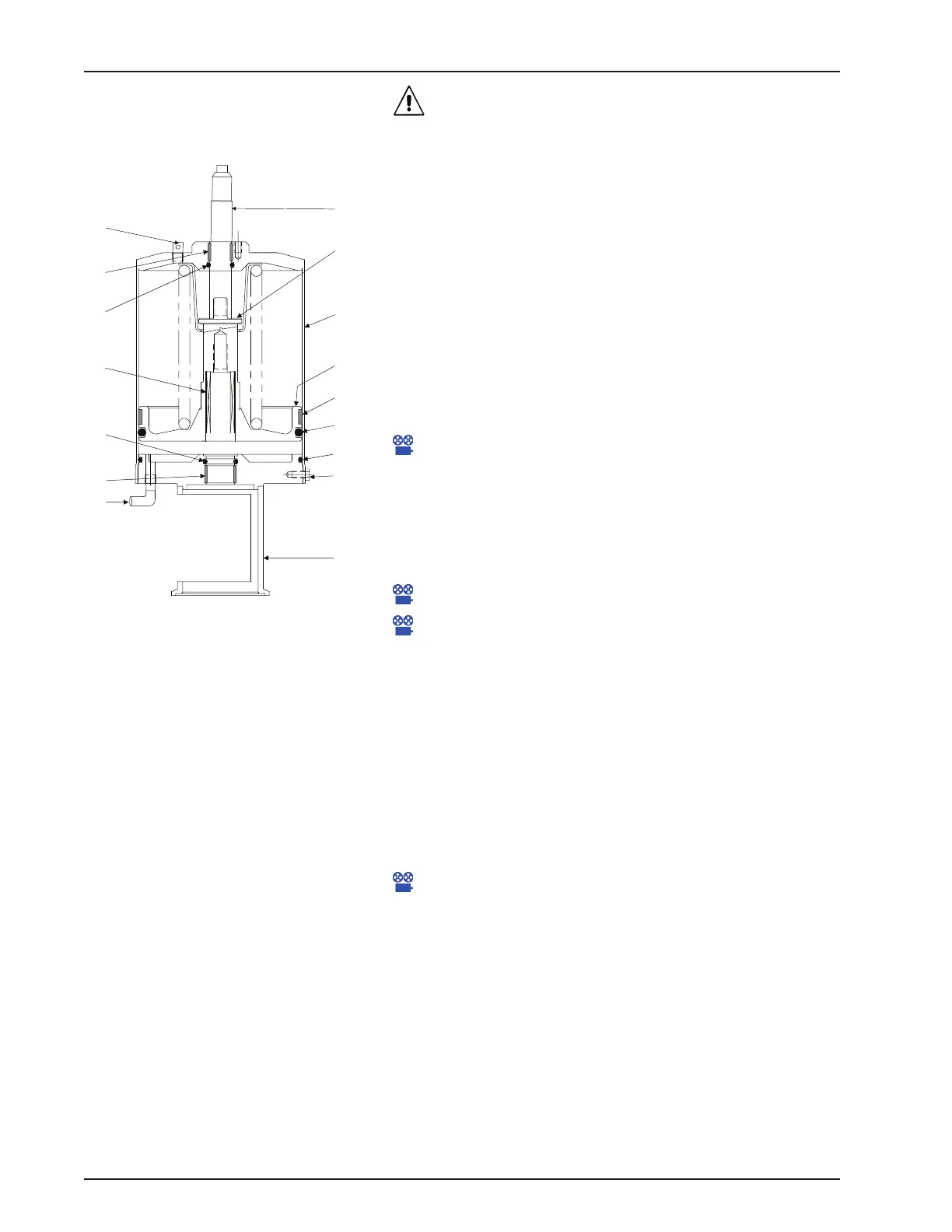
1. For non-seat lifting valves, remove the cap screws (Figure
26, item 9) and remove the yoke (item 12) from the cylinder
assembly. Set the yoke aside.
Maintenance Video 14: Actuator disassembly; lower
cartridge removal
2. Pull the piston and spring assembly (Figure 26, item 10) from
the cylinder assembly.
3. Inspect the four o-rings (Figure 26, items 6, 7, 8, and 11).
Replace them if they are worn or damaged.
Maintenance Video 17: Main piston o-ring removal
Maintenance Video 18: Main piston o-ring replacement with
bearing
4. Inspect the three bearings (Figure 26, items 5, 14, and 15). If
the bearing does not extend slightly above the edge of the
metal surface, replace the bearing.
NOTE: The bearing will be damaged
during removal and must be replaced
with a new bearing.
5. The bearing is split to allow its removal from the groove.
Place a screwdriver behind the bearing and pry it away from
the wall of the yoke. A needle-nose pliers can be used to grip
the bearing for removal.
NOTE: In
stallation of the piston and
spring assembly on 4" actuators requires
a special sleeve to contain the bearing
on the piston while installing the
assembly. See Figure 28 and Figure 29
on page 30.
6. For non-seat lifting valves, assemble the stack components
as shown in Figure 26. Install the yoke and cap screws.
Maintenance Video 22: Using insertion sleeve for W71/W73
Actuators
NOTE: For larger drawings and complete partlists, see “W71/
W73 Non-Seat Lift Actuator” on page 76 and “W72RS Non Seat
Lift Actuator” on page 80.
Figure 26 - W71/W73 Actuator Assembly
(Non-Seat Lift Valve)
5
6
11
9
7
8
14
10
4
12
31
 Loading...