Waukesha Cherry-Burrell Operation
10/2012 95-03087 Page 17
Automatic Fail-Safe
System
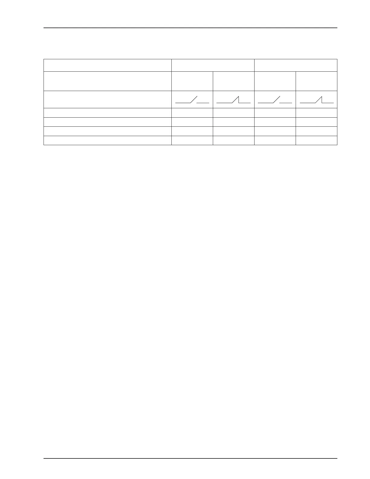
Table 4: Valve Stem Detection Conditions
W71/W73 W72RS/W72RSP
Condition
Upper
Sw
itch (NO)
Lower
Switch (NC)
Upper
Switch (NO)
Lower
Switch (NC)
Switch Symbol
Valve Closed 0 1 0 1
Valve Open 1 0 1 0
Valve Closed with Upper Seat Clean * 0 1 0 0
Valve Closed with Lower Seat Clean * 0 0 0 1
Notes:
1 = Energized, LED is lit; 0 = De-energized, LED is off
Upper Switch: Sends an input signal when the valve is properly
open.
Lower Switch: Sends an input signal when the valve is properly
closed.
Additional Switch: A third yoke-mounted proximity switch is avail-
able for additional signal feedback.
* W71/W73 Valves: Seat lift during both upper and lower seat
clean; indicator stem raises;
W72RS/W72RSP Valves: Seat lift during upper seat clean; seat
push during lower seat clean, indicator stem lowers.
Test Procedures
Positive Fail-Safe Detection Test
Perform a test to verify the fully closed fail-safe position. The
valve plug feedback proximity switches should be set for the fully
opened and fully closed positions of the valve. See Figure 9 on
page 16 for port and corresponding chambers.
Decommission the system, drain the lines and lock out the
pu
mps.
1. With the valve fully closed, confirm that the proximity
switches conform to Table 4. Verify the switch status on the
PLC control system.
2. Pressurize chamber 1 to open the valve (Figure 9, page 16).
Confirm that the proximity switches conform to Table 4. Verify
the switch status on the PLC control system.
3. Vent chamber 1 to close the valve.
4. If used, activate the upper seat lift either through the control
system o
r by supplying air to port 2.
5. When the upper seat lifts, confirm that the proximity switches
conform to the values in Table 4. If the yoke area does not
have a limit switch, visually confirm the upper seat lifting.
 Loading...