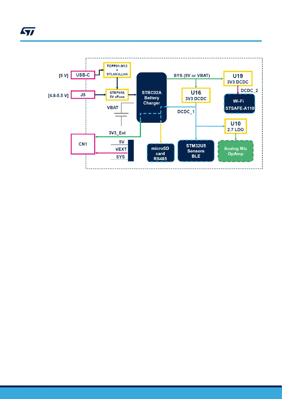
Figure 18. STWIN.box core system board - power supply block diagram
1.6.3.10 Power on or off procedure
If the STWIN.box core system board is not powered via a battery
, the board turns on or off when you connect or
disconnect an external supply, respectively.
Follow the steps below to power the board on and off when it is powered by a LiPo battery.
Step 1. Push the power (PWR) button for about a second to power the board on.
The wake-up hardware feature of the STBC02 battery charger manages the power on.
Step 2. Push the power button again to turn the board off.
The STM32 manages the power off feature via software. Thus, the application code running on the
STM32 needs to detect the push action in order to send the shutdown command to the battery charger
to switch the power supply off.
1.6.3.11 Power consumption evaluation
The STWIN.box features several test points and jumpers to monitor the electrical performance of the running
applications. In particular
, four resistors monitor the current consumption in each of the four main power supply
domains of the board.
To evaluate the general power consumption, remove both the battery and the USB cable, and directly provide 5 V
to the J5 connector.
Remove (unsolder) the below mentioned resistors to connect an ammeter. The resistor pads are conveniently
designed at a distance of 2.54 mm to facilitate soldering a standard header connector:
• R46 (3V3_SENSORS): all sensors except the analog microphone;
• R47 (VDD_UC): STM32 VDD (except VDDA);
• R48 (VDD_BLE): BlueNRG-M2 module;
• R49 (VDD_WIFI): Wi-Fi module.
There are also two solder bridges in series to the output of the two DC-DC regulators:
• SB15: DCDC_1
• SB18 (BlueNRG-M2): DCDC_2
UM2965
Functional blocks
UM2965 - Rev 1
page 21/58