List of figures
Figure 1. STWIN.box mounted with the plastic case .................................................1
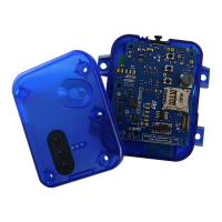
Figure 2. STEV
AL-STWINBX1 components .......................................................3
Figure 3. Layout of the core system board top components ............................................3
Figure 4. Layout of the core system board bottom components .........................................4
Figure 5. STEVAL-STWINBX1 block diagram......................................................4
Figure 6. STEVAL-STWINBX1 evaluation kit (top view) ...............................................5
Figure 7. STEVAL-STWINBX1 evaluation kit (bottom view) ............................................5
Figure 8. STEVAL-STWINBX1 - overview of the sensing components .....................................6
Figure 9. STEVAL-STWINBX1 - sensors on the top side ..............................................6
Figure 10. STEVAL-STWINBX1 - sensors on the bottom side ...........................................7
Figure 11. Main connectivity components and the STM32U585AI processing unit............................. 12
Figure 12. MCU and connectivity components (top view).............................................. 12
Figure 13. MCU and connectivity components (bottom view) ........................................... 13
Figure 14. MXCHIP EMW3080 ............................................................... 15
Figure 15. Power management of the STWIN.box core system board ..................................... 17
Figure 16. Power and protections.............................................................. 17
Figure 17. BATT1 connector ................................................................. 20
Figure 18. STWIN.box core system board - power supply block diagram ...................................21
Figure 19. STWIN.box core system resistors and solder bridges (top view) ................................. 22
Figure 20. STWIN.box core system resistors and solder bridges (bottom view) .............................. 22
Figure 21. Mapping of the 34-pin connector resources ............................................... 23
Figure 22. Connecting the core system board to the battery............................................ 25
Figure 23. STWIN.box core system board placed in the bottom case .....................................26
Figure 24. STWIN.box assembly ..............................................................27
Figure 25. STWIN.box mounted with the plastic case ................................................ 27
Figure 26. STM32CubeProgrammer - USB mode selection ............................................29
Figure 27. STM32CubeProgrammer - connection................................................... 29
Figure 28. STM32CubeProgrammer - programming ................................................. 30
Figure 29. STWIN.box and STLINK-V3MINI programmer ............................................. 30
Figure 30. STWIN.box, adapter, and STM32 Nucleo development board................................... 31
Figure 31. STWIN.box and ST-LINK/V2 debugger (JTAG 20-pin 2.54 mm pitch connector) ...................... 31
Figure 32. STWIN.box antenna ............................................................... 33
Figure 33. Firmware upgrade procedure ......................................................... 34
Figure 34. Core system board circuit schematic (1 of 8) ..............................................35
Figure 35. Core system board circuit schematic (2 of 8) ..............................................36
Figure 36. Core system board circuit schematic (3 of 8) ..............................................37
Figure 37. Core system board circuit schematic (4 of 8) ..............................................38
Figure 38. Core system board circuit schematic (5 of 8) ..............................................39
Figure 39. Core system board circuit schematic (6 of 8) ..............................................40
Figure 40. Core system board circuit schematic (7 of 8) ..............................................41
Figure 41. Core system board circuit schematic (8 of 8) ..............................................42
Figure 42. Adapter board circuit schematic ....................................................... 43
UM2965
List of figures
UM2965 - Rev 1
page 57/58