1.6.3.12 Buttons and LEDs
The STWIN.box core system board includes buttons and LEDs for user interaction:
•
buttons:
– USR: generic user button;
– PWR: connected to the STBC02 for integrated wake-up function and to the STM32 as a generic user
button;
– RESET: connected to the STM32 reset pin (black);
• LEDs:
– LED_C: red LED connected to the STBC02 for battery status feedback;
– LED1: green LED connected to the STM32;
– LED2: orange LED connected to the STM32.
1.6.3.13 34-pin expansion connector
The STWIN.box board also features a high current board-to-FPC/board-to-board (0.4 mm pitch) 34-pin connector
.
This connector is shared among few other evaluation kits such as STEVAL-PROTEUS1 and STEVAL-ASTRA1B
and allows expanding the platform functionality.
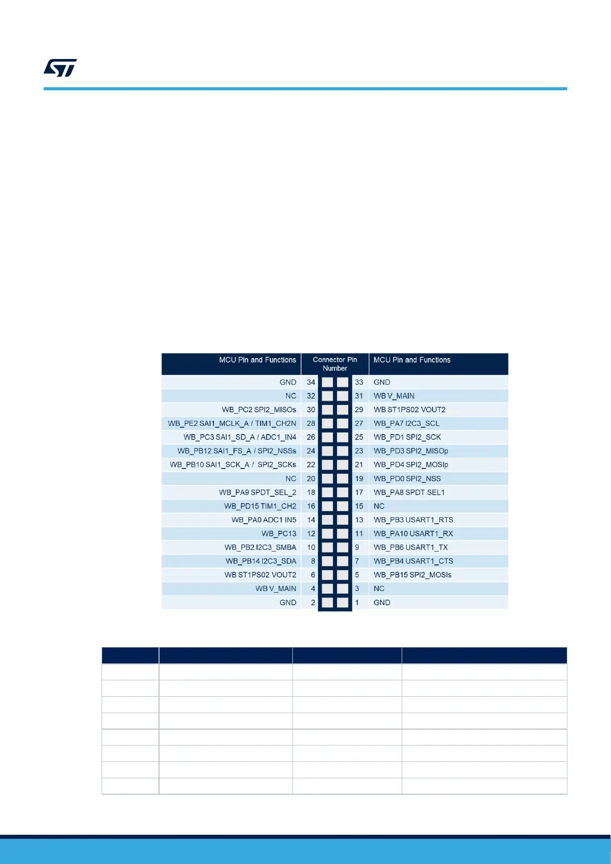
Figure 21. Mapping of the 34-pin connector resources
Table 17. Flexible expansion connector pins
Pin no. Description STM32 pin Signal
1 GND - -
2 GND - -
3 Not used - -
4 VCONN - 5V/SYS
5 SPIx_MOSIs PB15 SPI2_MOSI_p2
6 V REG1 - 3V3_Ext
7 USART_CTS PD11 USART3_CTS
8 I2Cz_SDA PG8 I2C3_SDA
UM2965
Functional blocks
UM2965 - Rev 1
page 23/58