6 Debug management
The serial wire/JTAG debug port (SWJ-DP) is an Arm
®
standard CoreSight
™
debug port.
The host/target interface is the hardware equipment that connects the host to the application board. This interface
is made of three components: a hardware debug tool, a serial-wire connector, and a cable connecting the host to
the debug tool.
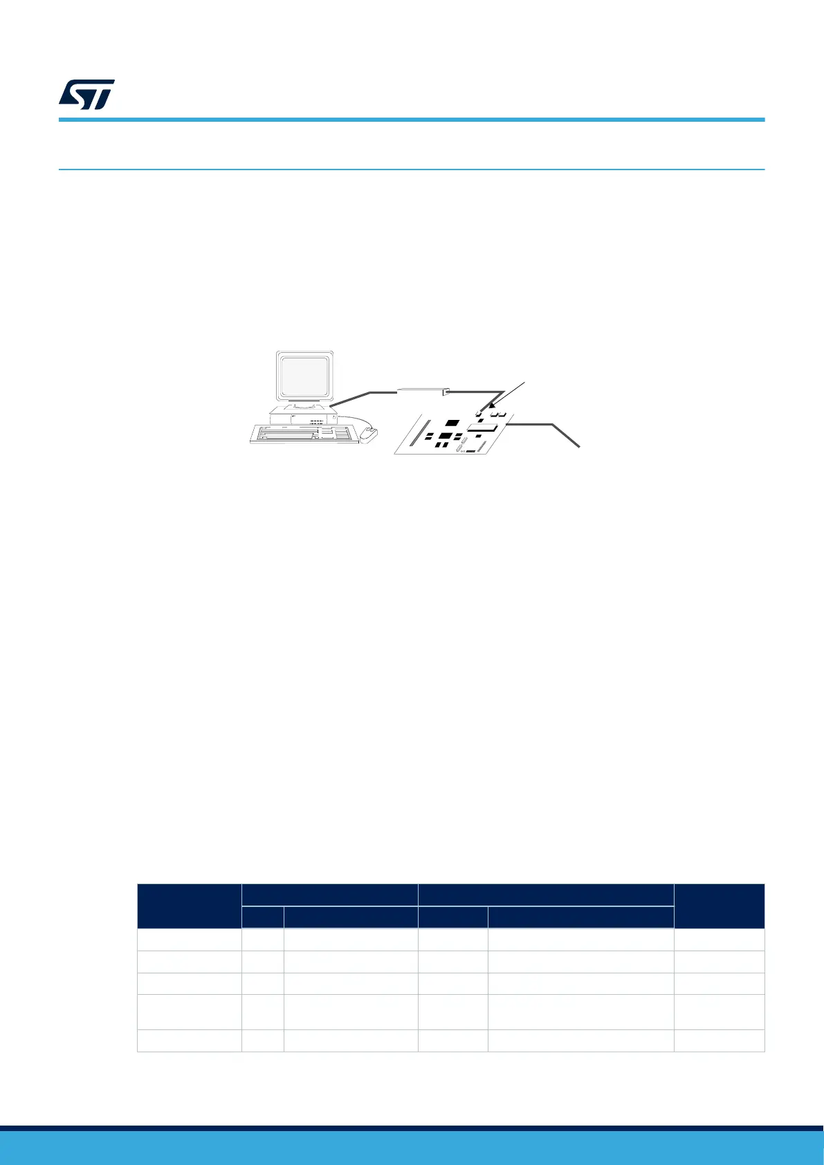
The figure below shows the connection of the host to a development board.
Figure 14. Host-to-board connection
DT67885V1
STM32 board
Host PC
Power supply
JTAG/serial-wire connector
Debug tool
The Nucleo demonstration board embeds the debug tools (STLINK), so it can be directly connected to the PC
through a USB cable.
6.1
SWJ-DP (serial-wire and JTAG debug port)
The SWJ-DP combines:
• a JTAG‑DP that provides a 5-pin standard JTAG interface to the AHP-AP port
• an SW-DP that provides a 2-pin (clock + data) interface to the AHP-AP port
In the SWJ-DP, the two JTAG pins of the SW-DP are multiplexed with some of the five JTAG pins of the JTAG-DP.
Note: The software can configure all SWJ-DP port I/Os to other functions, but debugging is no longer possible.
6.2
Pinout and debug port pins
The devices are offered in various packages with different numbers of available pins. As a result, some
functionality related to the pin availability may differ from one package to another.
6.2.1 SWJ-DP pins
Five pins are used as outputs for the SWJ-DP, as alternate functions of the GPIOs (general-purpose I/Os). These
pins, detailed in the table below, are available on all packages.
Table 6. Debug port pin assignment
SWJ-DP pin
JTAG debug port SW debug port
Pin assignment
Type Description Type Debug assignment
JTMS/SWDIO
Input JTAG test mode selection Input/Output Serial‑wire data input/output
PA13
JTCK/SWCLK Input JTAG test clock Input Serial‑wire clock PA14
JTDI Input JTAG test data input - - PA15
JTDO/TRACESWO Output JTAG test data output -
TRACESWO if asynchronous trace
is enabled
PB3
JNTRST Input JTAG test nReset - - PB4
AN5373
Debug management
AN5373 - Rev 6
page 30/47
 Loading...


