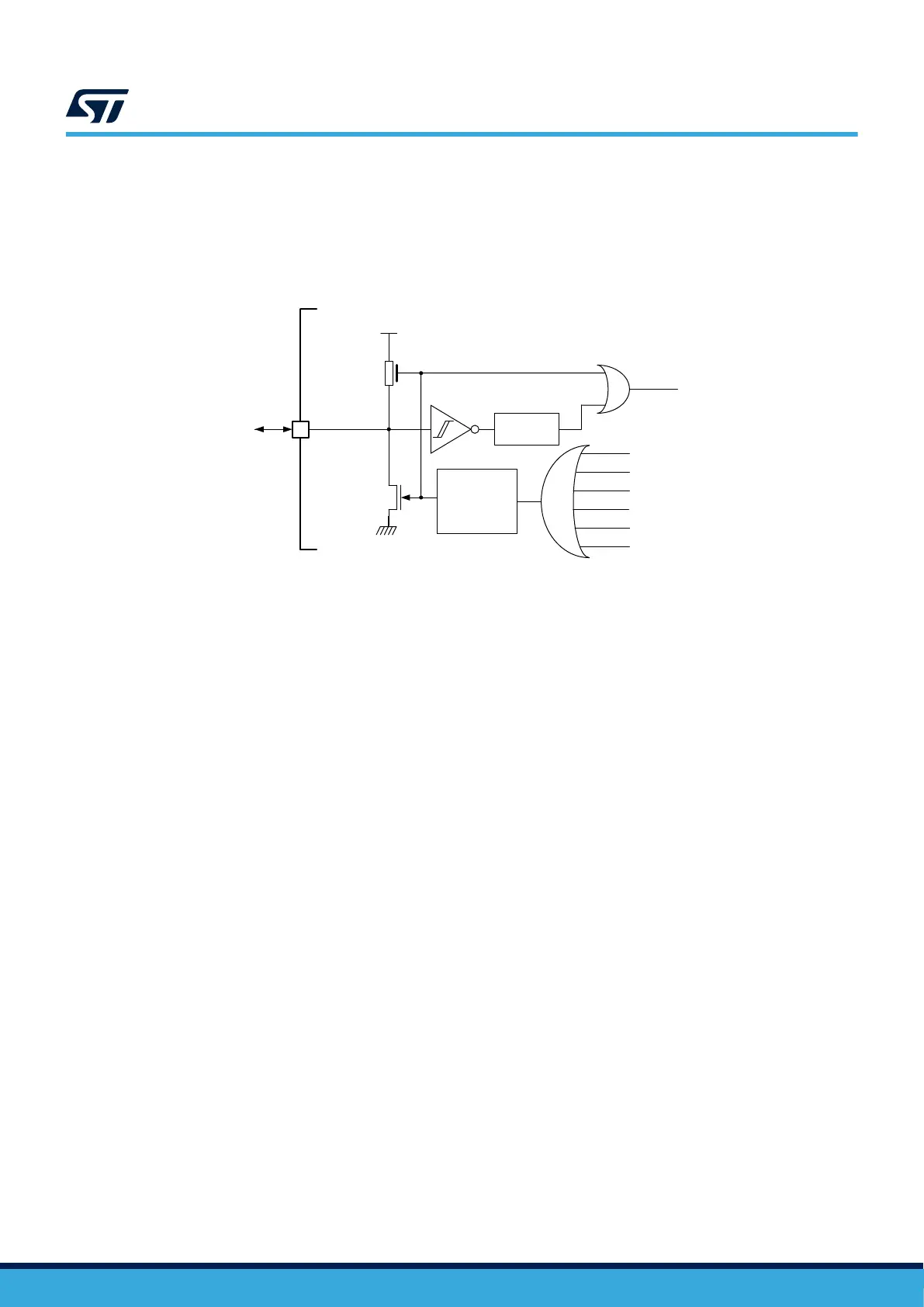
The system reset signal provided to the device is output on the NRST pin. The pulse generator guarantees a
minimum reset pulse duration of 20 μs for each internal reset source. In case of an external reset, the reset pulse
is generated while the NRST pin is asserted low.
In case of an internal reset, the internal pull-up RPU is deactivated in order to save the power consumption
through the pull-up resistor.
Figure 13. Simplified diagram of the reset circuit
DT40966V1
External
reset
V
DD
R
PU
WWDG reset
Software reset
Low-power manager reset
IWDG reset
Option byte loader reset
Pulse
generator
(min 20 μs)
NRST
System reset
Filter
BOR
2.4.3 Backup domain reset
A backup domain reset is generated when one of the following events occurs:
• a software reset, triggered by setting the BDRST bit in RCC_BDCR
• a V
DD
or V
BAT
power-on, if both supplies have previously been powered off
A backup domain reset only affects the LSE oscillator, RTC and TAMP, backup registers, the backup SRAM, and
RCC_BDCR and PWR_BDCR1.
AN5373
Reset and power-supply supervisor
AN5373 - Rev 6
page 20/47

 Loading...


