Table 10 lists the components in the STM32U599 discovery kit STM32U599J-DK (reference design MB1662)
based on STM32U599xxxxQ device, with SMPS (see Figure 20).
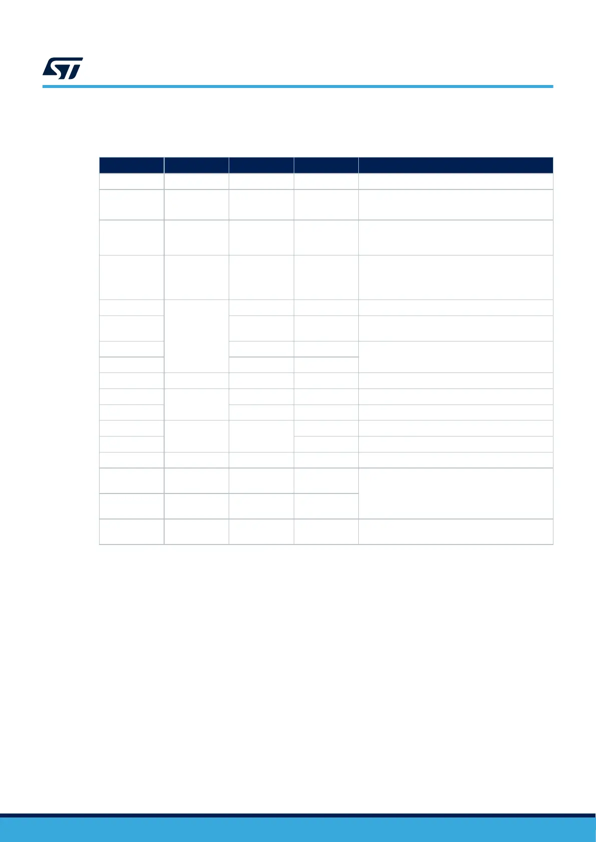
Table 10. Components of STM32U599 discovery kit
Reference Type Value Quantity Comments
B1 Push-button - 1 -
C4, C6
Ceramic
capacitor
1 µF 2
Decoupling capacitors
C6 used for the internal VREFBUF
C2, C16
Tantalum or
ceramic
capacitor
10 µF 2 Decoupling capacitors required for the package
C1, C3 (x10),
C5, C7, C8,
C13, C17, C21,
C22, C23
Ceramic
capacitor
100 nF 19 For each external power pin
C20
Tantalum or
ceramic
capacitor
4.7 µF 1 Decoupling capacitor
C18, C19 2.2 µF 2
Required on each VDD11 pin of packages with
SMPS
C11, C12 3.9 pF 2
Used for LSE: the value depends on the crystal
characteristics (refer to document [3])
C9, C10 6.8 pF 2
L1 Coil 2.2 µH 1 Required for SMPS packages on VLXSMPS pin
X1
Quartz
32.768 kHz 1 Used for LSE
X2 16 MHz 1 Used for HSE
R1
Resistor 10 KΩ
1 Used to limit the current on VBAT pin
R2, R3, R4 3 Used for the ST‑LINK interface
SW1 Switch - 1 Used to select the right boot mode
U1, U2, U3
ESD protection
6V1
- 3
Used for ESD protection
R5, R6, R7, R8,
R9
- 47 Ω 5
P1
ST LINK V2
connector
- 1 Used to connect an external ST‑LINK
AN5373
Design reference for a STM32U5 device (with and without SMPS)
AN5373 - Rev 6
page 40/47

 Loading...


