8.2 Design reference for a STM32U5 device (with and without SMPS)
Table 9 lists the components used for a STM32U5 design reference :
• based on STM32U535/545/575/585xxxxQ device, with SMPS (see Figure 18)
• based on a STM32U5xxx device, without SMPS (see Figure 19)
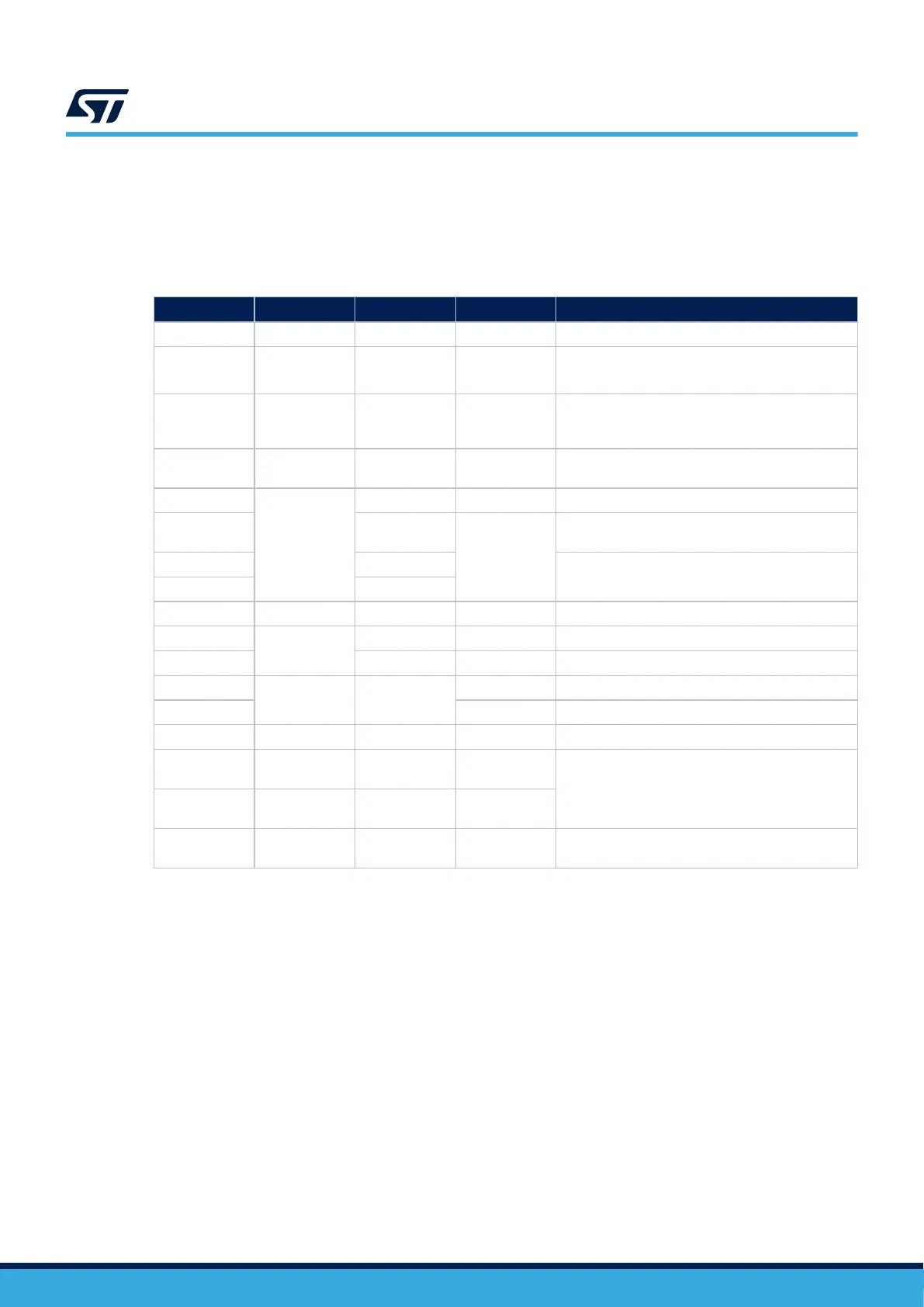
Table 9. Components of STM32U5 device design reference
Reference Type Value Quantity Comments
B1 Push-button - 1 -
C1, C4, C6
Ceramic
capacitor
1 µF 3
Decoupling capacitors
C6 used for the internal VREFBUF
C2, C16
Tantalum or
ceramic
capacitor
10 µF 2 Decoupling capacitors required for the package
C3 (x5), C5, C7,
C8, C13, C17
Ceramic
capacitor
100 nF 10 For each external power pin
C15
Tantalum or
ceramic
capacitor
4.7 µF 1 Decoupling capacitor
C18, C19 2.2 µF
2
Required on each VDD11 pin of packages with
SMPS
C11, C12 3.9 µF
Used for LSE: the value depends on the crystal
characteristics (refer to document [3])
C9, C10 6.8 pF
L1 Coil 2.2 µH 1 Required for SMPS packages on VLXSMPS pin
X1
Quartz
32.768 kHz 1 Used for LSE
X2 16 MHz 1 Used for HSE
R1
Resistor 10 KΩ
1 Used to limit the current on VBAT pin
R2, R3, R4 3 Used for the ST‑LINK interface
SW1 Switch - 1 Used to select the right boot mode
U1, U2, U3
ESD protection
6V1
- 3
Used for ESD protection
R5, R6, R7, R8,
R9
- 47 Ω 5
P1
ST LINK V2
connector
- 1 Used to connect an external ST‑LINK
AN5373
Design reference for a STM32U5 device (with and without SMPS)
AN5373 - Rev 6
page 37/47

 Loading...


