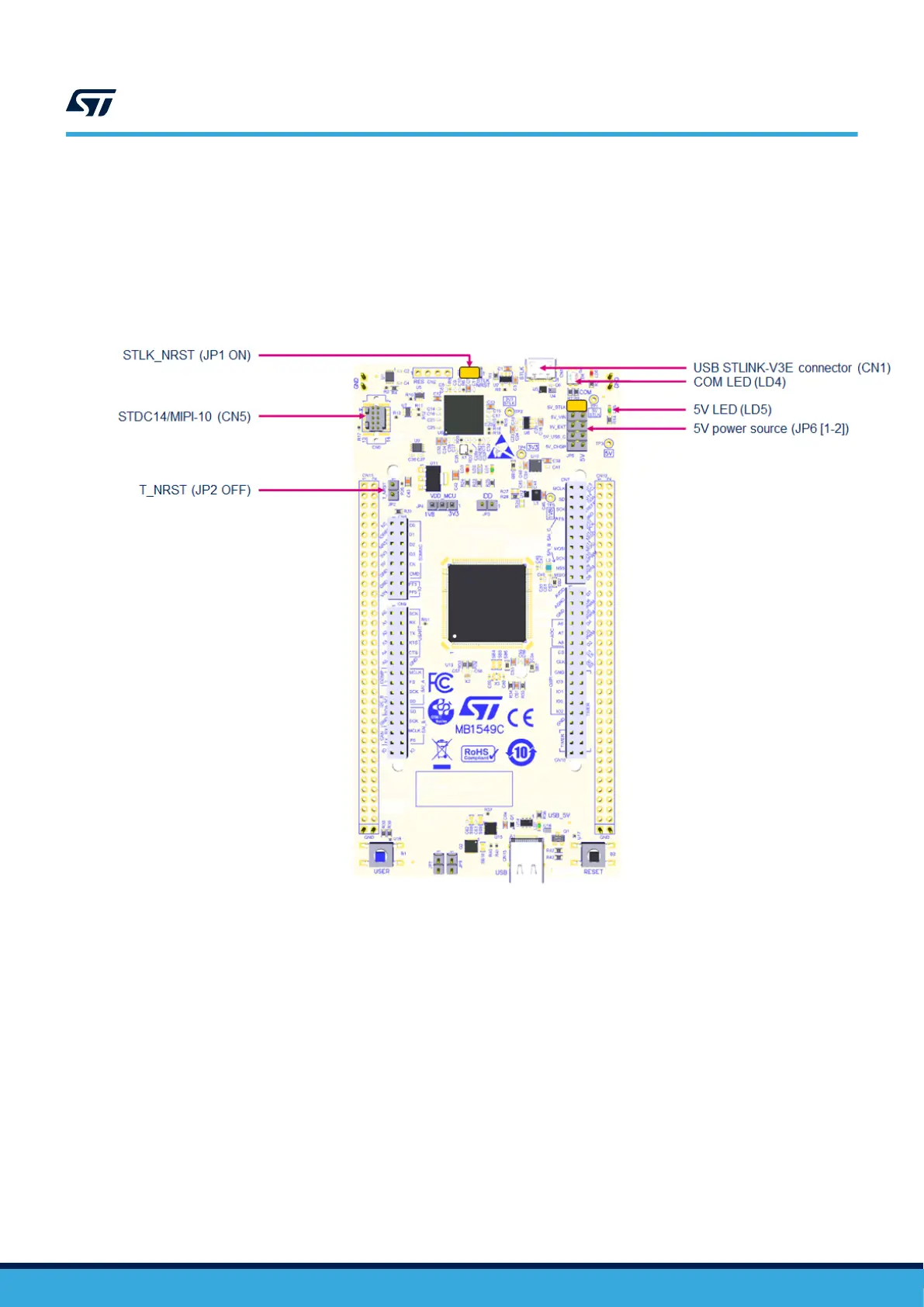
6.3.3 Using an external debug tool to program and debug the on-board STM32
There are two basic ways to support an external debug tool:
1. Keep the embedded STLINK-V3E running. Power on the STLINK-V3E at first until the COM LED turns red.
Then connect the external debug tool through the CN5 STDC14/MIPI-10 debug connector
2. Set the embedded STLINK-V3E in a high-impedance state. When the JP1 STLK_RST jumper is ON, the
embedded STLINK-V3E is in RESET state and all GPIOs are in high impedance. Remove JP2 to avoid
driving MCU T_NRST. Then, connect the external debug tool to the CN5 STDC14/MIPI‑10 debug connector.
Figure 8. Connecting an external debug tool to program the on-board STM32U5
UM2861
Embedded STLINK-V3E
UM2861 - Rev 2
page 15/49