6 Hardware layout and configuration
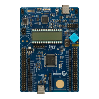
The STM32U5 Nucleo-144 board is designed around an STM32U5 microcontroller in an LFQFP 144-pin package.
Figure 3 shows the connections between the STM32 and its peripherals (STLINK-V3E, push‑buttons, LEDs, USB
ST Zio connectors, and ST morpho headers). Figure 4 and Figure 5 show the location of these features on the
STM32U5 Nucleo-144 board.
The mechanical dimensions of the board are shown in Figure 6.
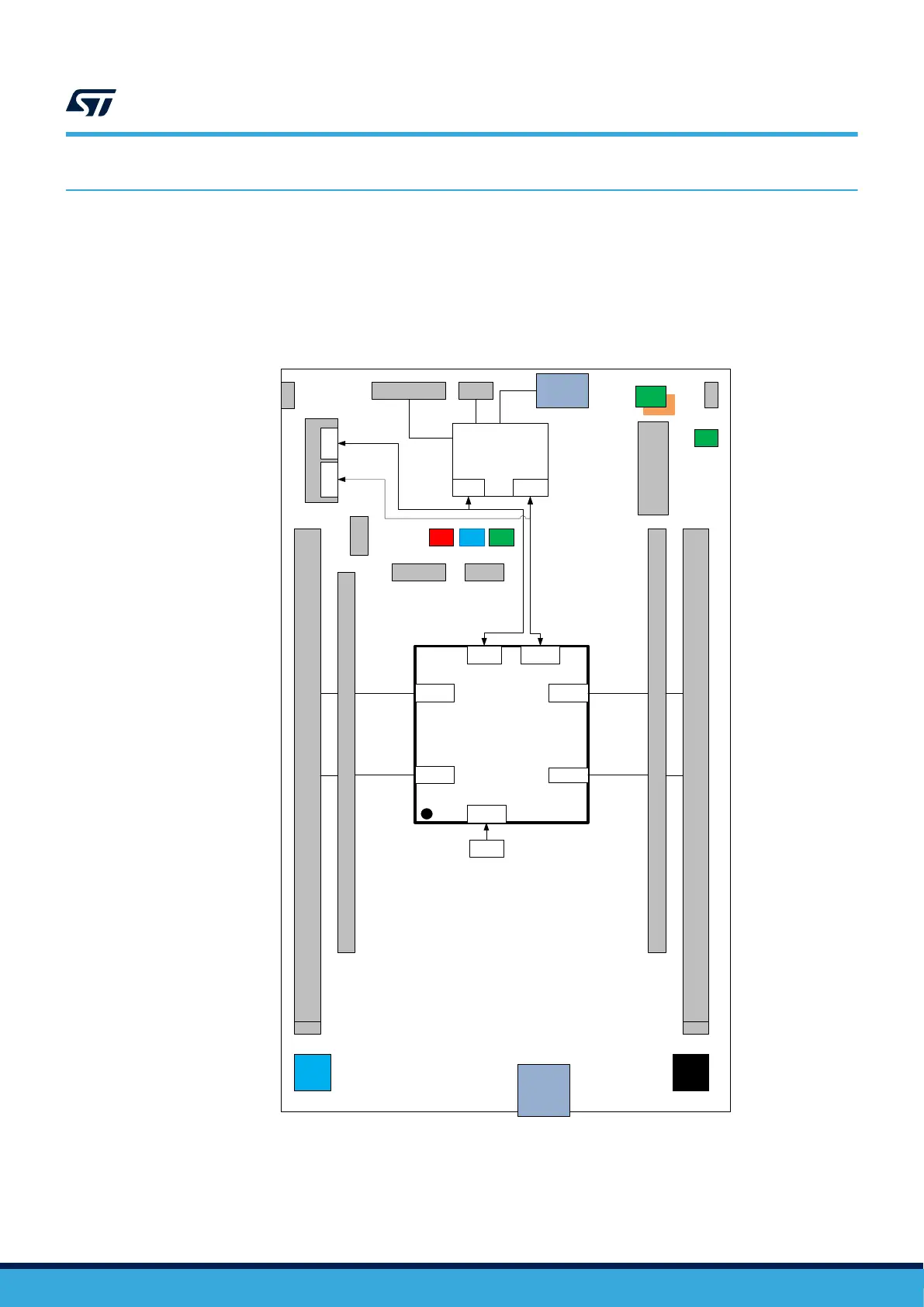
Figure 3. Hardware block diagram
STM32U575ZI-Q
OSC_32
SWD
32KHz
Crystal
VCP
UART
GPIOs
GPIO
LED
GPIO
Embedded
STLINK-V3E
STDC14/MIPI10
SWD
VCP
UART
USB MicroB
connector
B1
User
B2
RST
ARDUINO
MORPHO
GPIO
ARDUINO
MORPHO
5V
PWR SEL
5V
LED
RES
COM
T_NRST
STLK
NRST
LEDLED
IDD1V8 / 3V3
USB Type C
connector
GND
GND
GNDGND
SWDUART
UM2861
Hardware layout and configuration
UM2861 - Rev 2
page 9/49