5 Quick start
The STM32U5 Nucleo-144 board is a low-cost and easy-to-use development kit, to quickly evaluate and start
development with an STM32U5 Series microcontroller in an LFQFP144-pin package. Before installing and using
the product, accept the Evaluation Product License Agreement from the www.st.com/epla webpage. For more
information on the STM32U5 Nucleo-144 board and demonstration software, visit the www.st.com/stm32nucleo
webpage.
5.1 Getting started
Follow the sequence below to configure the STM32U5 Nucleo-144 board and launch the demonstration
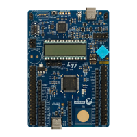
application (refer to Figure 4 for component location):
1. Check the jumper position on the board (refer to Default board configuration).
2. For the correct identification of the device interfaces from the host PC and before connecting the board,
install the STLINK-V3E USB driver available on the www.st.com website.
3. Connect the STM32U5 Nucleo-144 board to a PC with a USB cable (USB Type-A or USB Type-C
®
to
Micro-B) through the USB connector CN1 to power the board.
4. The LD5 5V_PWR green LED and LD4 COM LED light up, and the green LD1 blinks.
5. Press the B1 blue user button.
6. Observe how the blinking of the LEDs LD1, LD2, and LD3 changes, according to clicks on button B1.
7. Download the demonstration software and several software examples that help to use the STM32 Nucleo
features. These are available on the www.st.com website.
8. Develop your application using the available examples.
5.2 Default board configuration
By default, the STM32U5 Nucleo-144 board is configured with VDD_MCU@3V3. It is possible to set the board for
VDD_MCU@1V8. Before switching to 1V8, check that the extension module and external shield connected to the
NUCLEO board are 1.8 V compatible.
The default jumper configuration and voltage setting are shown in Table 4.
Table 4. Default jumper configuration
Jumper Definition Default position Comment
JP1 STLK_NRST OFF STLINK-V3E MCU not under reset mode
JP2 T_NRST ON
RST connected between MCU target
and debugger
JP4 VDD [1-2] VDD MCU voltage selection 3V3
JP5 IDD measurement ON MCU VDD current measurement
JP6 5V power selection [1-2] 5V from STLINK-V3E
JP7 UCPD_DBCC1 OFF Refer to Section 6.11.2 UCPD.
JP8 UCPD_DBCC2 OFF Refer to section Section 6.11.2 UCPD.
UM2861
Quick start
UM2861 - Rev 2
page 6/49