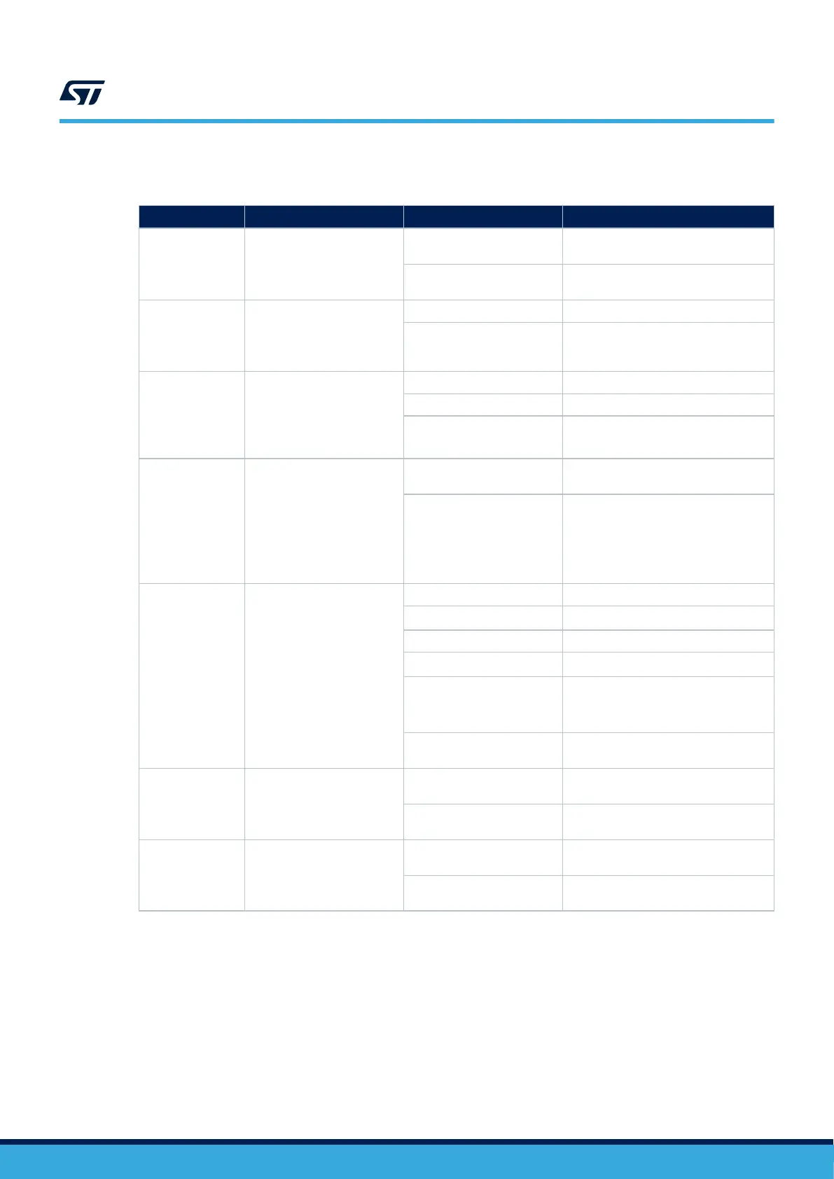
Table 5 explains the other jumper settings and configurations.
Table 5. Jumper configuration
Jumper Definition
Setting
(1)
Comment
JP1 STLK_RST
ON
Use to reset the STLINK-V3E MCU
when an external debug probe is used.
OFF
Normal mode: use the STLINK-V3E
debug probe
JP2 T_NRST
ON STLINK-V3E able to reset target MCU
OFF
STLINK-V3E not able to reset Target
MCU configuration to use when an
external debug probe is used.
JP4 VDD voltage selection
[1-2] VDD voltage selection is 3V3
[2-3] VDD voltage selection is 1V8
OFF
No internal VDD power supply
(External 3V3 or 1V8 needed)
JP5 IDD measurement
ON
MCU is powered by the on‑board
power supplies.
OFF
Use an ammeter to measure the MCU
power consumption, or connect an
external source 3V3 or 1V8 on pin
2 to supply the MCU (STLINK-PWR
tools with STM32CubeMonitor-Power or
ULPBench probe as exemple)
JP6 5V Power selection
[1-2] 5V source from STLINK-V3E
[3-4]
5V source from ARDUINO
®
VIN 7-12V
[5-6] 5V source from 5V_EXT
[7-8]
5V source from USB Type-C
®
[9-10]
5V source from USB_CHGR
(from CN1 STLINK-V3E USB connector
without overcurrent protection)
OFF
NO 5V power source, configuration
when external 3V3 is used.
JP7 UCPD_DBCC1
OFF
UCPD_DBCC1 NOT connected to
GND
ON
UCPD_DBCC1 connected to GND (For
debug purpose)
JP8 UCPD_DBCC2
OFF
UCPD_DBCC2 NOT connected to
GND
ON
UCPD_DBCC2 connected to GND (For
debug purpose)
1. The default configuration is in bold.
UM2861
Default board configuration
UM2861 - Rev 2
page 8/49