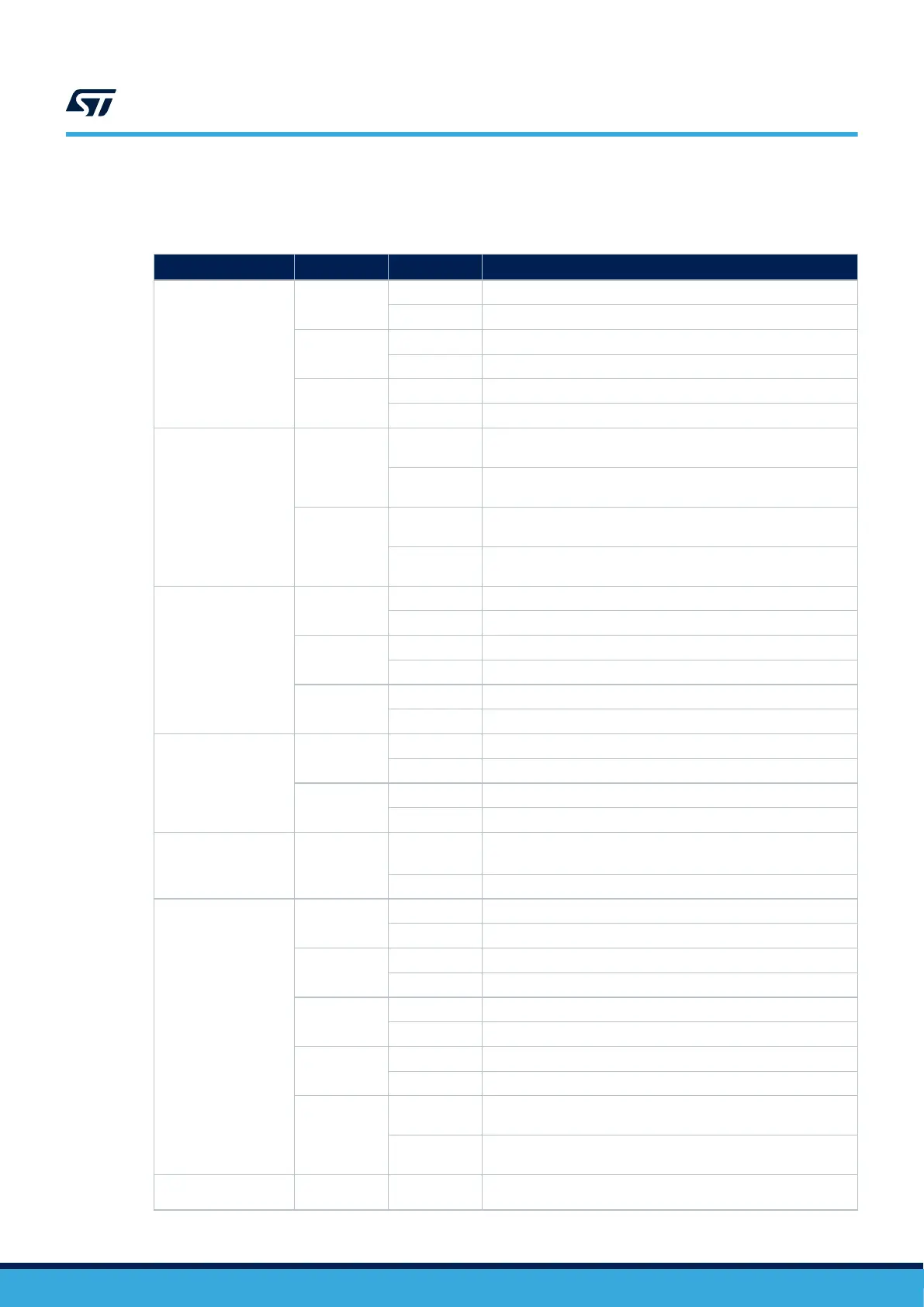
7.3 Solder bridge configuration for the expansion connector
Table 20 details the solder bridges of the STM32U5 Nucleo-144 board for the expansion connector.
Table 20. Solder bridge configuration
Definition Bridge
Setting
(1)
Comment
IOREF selection
SB16
OFF IOREF not connected to 1V8 power supply
ON IOREF connected to 1V8 power supply
SB17
OFF IOREF not connected to VDD power supply
ON IOREF connected to VDD power supply
SB18
OFF IOREF not connected to 3V3 power supply
ON IOREF connected to 3V3 power supply
SDMMC IO
PC8/PC9
SB19
OFF
PC8 not connected to CN12 ST morpho pin 2 to avoid stub on
CN8 Zio SDMMC_D0
ON
PC8 connected to CN12 ST morpho pin 2 and CN8 Zio pin 2:
SDMMC_D0 signal quality can be impacted
SB22
OFF
PC9 not connected to CN12 ST morpho pin 1 to avoid stub on
CN8 Zio SDMMC_D1
ON
PC9 connected to CN12 ST morpho pin 1 and CN8 Zio pin 4.
SDMMC_D1 signal quality can be impacted
ADC-A3 / QSPI_IO1
PB0
SB63
OFF PB0 not used as QSPI_IO1
ON PB0 used as QSPI_IO1
SB64
OFF PB0 not connected to ARDUINO A3
ON PB0 connected to ARDUINO A3
SB65
OFF PB0 not connected to ST morpho pin 34
ON PB0 connected to ST morpho pin 34
ADC_A1 / QSPI_CS
PA2
SB56
OFF PA2 not connected to Zio QSPI_CS
ON PA2 connected to Zio QSPI_CS
SB57
OFF PA2 not connected to ARDUINO A1
ON PA2 connected to ARDUINO A1
ADC-A7 /
VBUS_SENSE
PC2
SB53
OFF
PC2 not connected to ADC_A7 on Zio connector and used as
USB Type-C
®
VBUS_SENSE (SB6)
ON PC2 connected to ADC_A7 on Zio connector
Zio SAI_D / SPI_B
interface
SB35
OFF PA4 not connected to CN7 Zio pin 9 for SAI_D interface
ON PA4 connected to CN7 Zio pin 9 for SAI_D interface
SB38
OFF PA4 not connected to CN7 Zio pin 17 for SPI_B interface
ON PA4 connected to CN7 Zio pin 17 for SPI_B interface
SB36
OFF PB4 not connected to CN7 Zio for SAI_D interface
ON PB4 connected to CN7 Zio for SAI_D interface
SB43
OFF PB4 not connected to CN7 Zio for SPI_B interface
ON PB4 connected to CN7 Zio for SPI_B interface
SB37
OFF
PB5 not connected to CN7 Zio for SPI_B interface: Reserved for
UCPD_DBCC1
ON
PB5 connected to CN7 Zio for SPI_B interface, shared with for
UCPD_DBn and UCPB_DBCC1
QSPI_CLK /
TIMER_C_PWM2
SB61
OFF PB10 not used as QSPI_CLK
UM2861
Solder bridge configuration for the expansion connector
UM2861 - Rev 2
page 38/49