DocID16139 Rev 5 11/42
AN3029 Clock management
41
Crystal/ceramic resonator
• Frequency range: 1 to 16 MHz
• Stabilization time: Programmable from 1 to 4096 cycles
• Oscillation mode: Preferred fundamental
• Output duty cycle: Max 55/45%
• I/Os: Standard I/O pins multiplexed with OSC
IN
and OSC
OUT
• Cload: 10 to 20 pF
• Drive level maximum: at least 100 µW
The values of the load capacitors C
L1
and C
L2
are heavily dependent on the crystal type and
frequency. Refer to the datasheet of the crystal manufacturer to select the capacitances. For
best oscillation stability, C
L1
and C
L2
normally have the same value. Typical values are in
the range from below 20 pF up to 40 pF (cload: 10 to 20 pF). The parasitic capacitance of
the board layout also needs to be considered and typically adds a few pF to the component
values (refer to AN2867).
A clock security system prevents any CPU fatal error from a HSE failure, as it safely
switches to HSI.
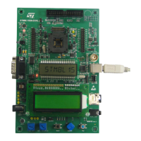
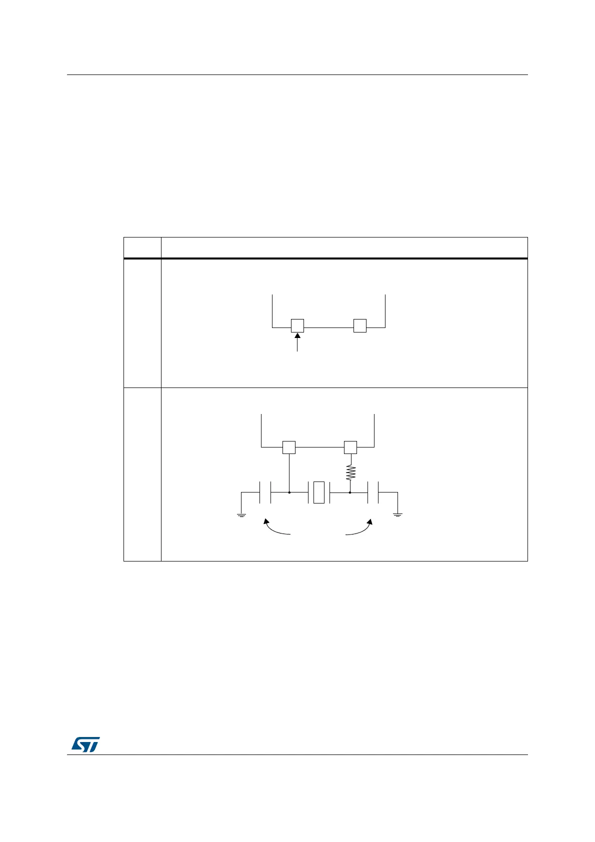
Figure 4. HSE clock sources
Hardware configuration
External clockCrystal/ceramic resonators
(1)
1. The value of R
EXT
depends on the crystal characteristics. A 0 Ω resistor works well with most oscillators
but, it is not optimal. A typical value is in the range 5 to 6 R
S
(resonator series resistance). To fine-tune the
R
EXT
value, refer to AN2867 (Oscillator design guide for ST microcontrollers).
MS32524V1
OSC
IN
OSC
OUT
External source
STM8
(I/O available)
MS32529V1
Load capacitors
STM8
C
L2
C
L1
Q1
OSC
IN
OSC
OUT
R
EXT
(1)