STM8 development tools AN3029
22/42 DocID16139 Rev 5
8.1.2 SWIM connector pins
The SWIM connector pins consist of four pins as described in Table 3.
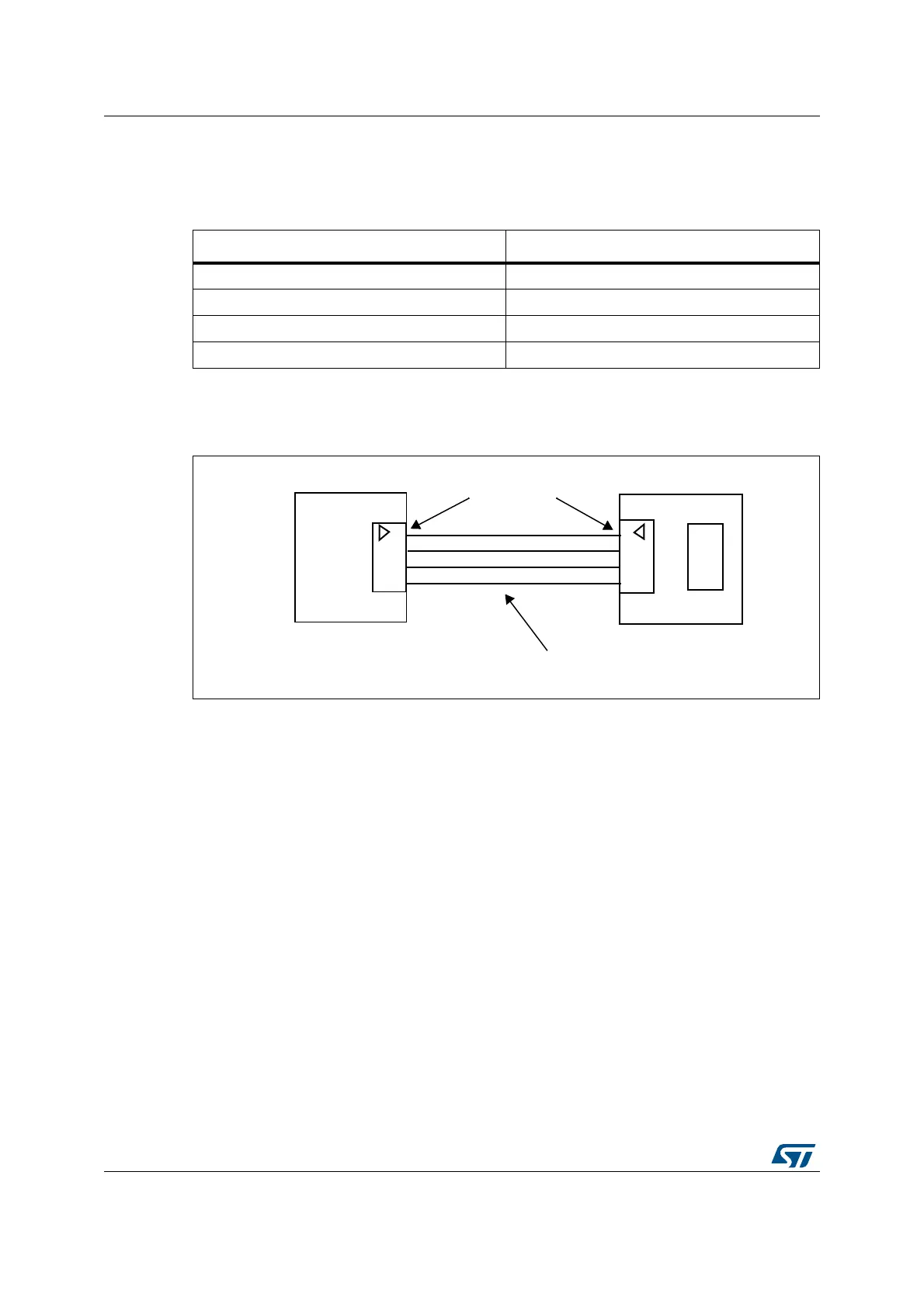
8.1.3 Hardware connection
Figure 12. Hardware connection
Caution: It is recommended to place the SWIM header as close as possible to the STM8L/STM8AL
device, as this minimizes any possible signal degradation caused by long PCB tracks.
Table 3. SWIM connector pins
Pin number Pin name
Pin 1 V
DD
Pin 2 SWIM pin
Pin 3 V
SS
Pin 4 Reset
MS32528V1
4
4
1
1
2
3
2
3
AD/ICC SWIM adapter
Application board
STM8
SWIM cable
V
DD
V
DD
SWIM connector