DISPLAY OPERATION
Display Front Panel
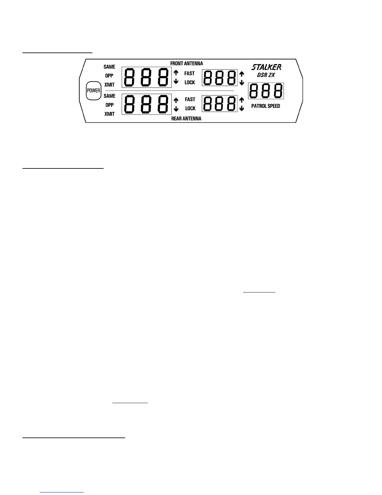
The S
DSR 2X display unit presents the radar operator with a clear and logically organized picture of how the unit is operating
and the targets that it is tracking. The operator knows in a glance the speed of the target, its direction of travel, and its position relative
to the patrol car. Display brightness can be set to “auto” or can be manually adjusted to compensate for ambient conditions. Other
features include:
Display Unit Functions
POWER: The POWER button is the main On/Off power switch. S DSR 2X has a jumper in its
power-supply circuit that selects one of the two following options:
1. When vehicle power is applied, the unit must be turned on by pressing the POWER switch.
This is the normal factory setting.
2. When vehicle power is applied, the unit always powers on automatically, but may be turned
off by pressing the POWER switch. If this setting is desired, call the factory.
TARGET WINDOWS: The two left, (orange) three-digit LED windows are the target windows. The top window displays
the speed of the strongest target entering the front radar beam, while the bottom window displays
the speed of the strongest target entering the rear radar beam. While in stationary mode, both
same lane and opposite lane targets can be monitored simultaneously for both front and rear
antennas. The four target areas are known as Target Zones. When a strong target is displayed in
either target window, an arrow icon located to the right of the window indicates the target’s
direction of travel relative to the patrol vehicle. In moving mode, two Target Zones can be
monitored, one front and one rear.
MIDDLE WINDOWS: The two middle, (red) three-digit LED windows are dual purpose
windows. First, they are used
for locking the strongest target shown in the corresponding left window. While not containing a
“locked” speed, the middle windows are used to display the faster target in the radar beams. The
LOCK and FAST icons are used to indicate the current status of the window.
The middle windows are used to store target speeds that the operator chooses to "lock" using the
appropriate front or rear LOCK key. The presence of the LOCK icon indicates that the middle
window contains a "locked" target speed. Every speed lock will be followed immediately by a 3-
word voice enunciator that indicates antenna/radar mode/direction.
Examples: FRONT/STATIONARY/CLOSING, FRONT/STATIONARY/AWAY,
REAR/STATIONARY/CLOSING, REAR/STATIONARY/AWAY,
FRONT/OPPOSITE/CLOSING, REAR/OPPOSITE/AWAY, FRONT/SAME/CLOSING,
FRONT/SAME/AWAY, REAR/SAME/CLOSING, OR REAR/SAME/AWAY.
Only one target speed can be locked.
PATROL WINDOW: The right, (green) three-digit LED window is the patrol window. In moving mode, the operator
should always
verify that the patrol window is tracking the patrol vehicle’s speedometer. After
locking a target speed, the patrol window may be "blanked" by pressing the PS BLANK key.
Restore the patrol speed by pressing the PS BLANK key a second time. Read the PS BLANK
key section for more information.
LED Icon Indicator Definition
XMIT: The XMIT icon indicates that the associated antenna is transmitting. When XMIT is turned off, HLd will
be displayed in the lock window (for that antenna) unless that antenna has a locked target.
7