HOW TO INITIATE A SELF-TEST
Self Testing Modes 2X Display Unit
Power-On Self-Test
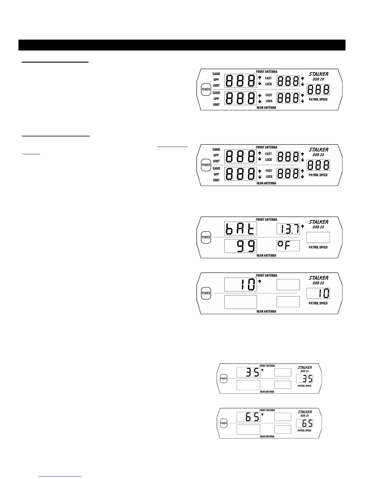
Each time the unit is powered on, an automatic self-test is performed
to verify that the unit functions. All displays indicate 888 (Fig. 40)
during the test. A 4-beep “happy” tone indicates the successful
completion of this test. If a problem is detected, FAIL will be
displayed along with a 20-beep tone. Immediately after power-on,
and while all display segments are illuminated, pressing the MENU
key will display the software version followed by the nominal
transmitter frequency.
Fig. 40
Internal Circuit Test
An internal circuit test can be performed at any time by pressing and
holding the TEST key. This performs a diagnostic check on the
display/counting unit (Fig. 41), the antennas, and antenna cables.
The display/counting unit will first perform a segment test, processor
check, memory check, and crystal accuracy check. Next the input
voltage and internal temperature is checked to verify they are within
limits. (Fig. 42) Following will be the display of speeds 10, 35, and
65 (Figures 43, 44, and 45).
Fig. 41
Fig. 42
Fig. 43
Fig. 44
Fig. 45
33