40
EN
1.7 Notices Regarding the Emergency Stop Switch
The emergency stop switch of STEPCRAFT machines is to be found on the front side of the machine or in a separate
housing. This depends on the machine series. Refer to the manual of your machine for more information.
If you would like to use a system-guided tool like a milling motor of another supplier which is equipped with
a separate ON / OFF switch and is NOT controlled via the PC, you have to make sure that it is professionally
connected to the emergency stop switch. Neglecting this will cause the tool to continue running even if you
actuate the emergency stop switch. There is a considerable risk for personal or material damages!
The emergency stop switch can only effect the stop of all components if these components are electronically
connected with the emergency stop switch. Be sure to test the functionality of the emergency stop switch
before using the machine. The switch has to be capable of stopping the entire machine in case of an emer-
gency!
By pressing the emergency stop switch, the emergency stop is triggered. The power supply of the control is interrupted.
Additionally, the control software receives the signal to stop the operating process. The machine and milling motor stop
immediately. An emergency stop will result in the stepper motors losing steps. Your machine has to be homed afterwards!
To cancel the emergency stop state, turn the emergency stop switch clockwise. This reactivates the control system. A
controlled stop of the machine can only be achieved via the control software. If you want to use a system-guided tool,
such as a milling and drilling motor, that features a separate ON / OFF switch and that is NOT controlled via the PC, you
have to make sure that it is expertly connected with the emergency stop switch, for example by use of a switch unit for
electric consumers (EU item 10052, US item 10129).
If you do not comply with these requirements, the system-guided tool will continue to run although you have activated the
emergency stop switch leading to a high risk of personal injury and damage to property! If you are using third-party prod-
ucts, such as another CNC router mainboard, you are solely responsible for connecting the emergency stop functionality
properly to the CNC machine. If you have any questions, please do not hesitate to contact us! You can nd our contact
details on the cover sheet or in chapter „10 Contact“.
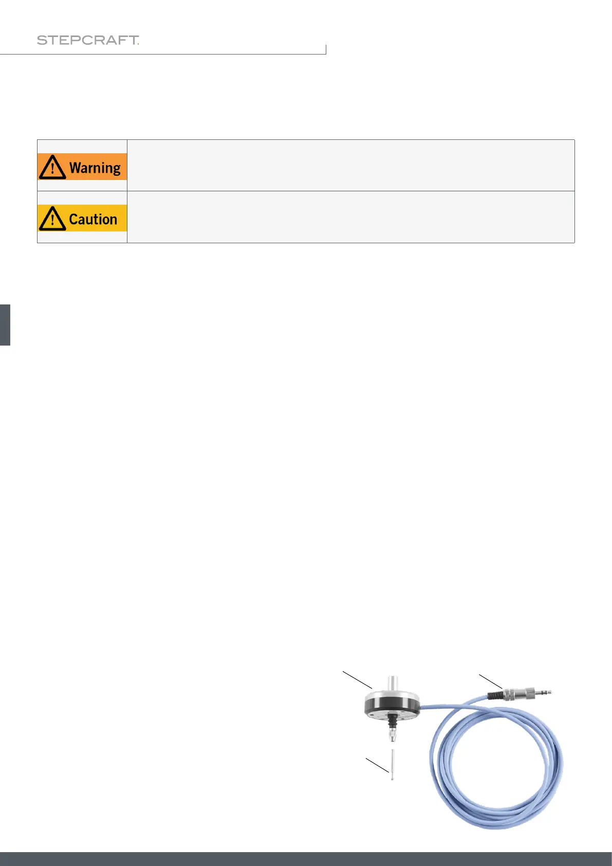
2 Description
The 3D touch probe makes it possible to record non-planar surfaces electronically and to precisely sense three-dimen-
sional bodies. This way, objects can be reproduced and arched surfaces can be engraved in an easy and simple manner,
due to surface compensation. Additionally, the sensitivity of the probe tip can be set individually. The housing has a
diameter of 43 mm and the fastening spigot a diameter of 8 mm. The spherical probe tip has a measurement of 2 mm.
The connection to a machine is easy to establish by use of the 3.5 mm jack plug.
2.1 Scope of Delivery
1
2
3
1. 3D touch probe housing with cable
2. 3,5 mm jack plug (not assembled)
3. 3D touch probe tip