47
EN
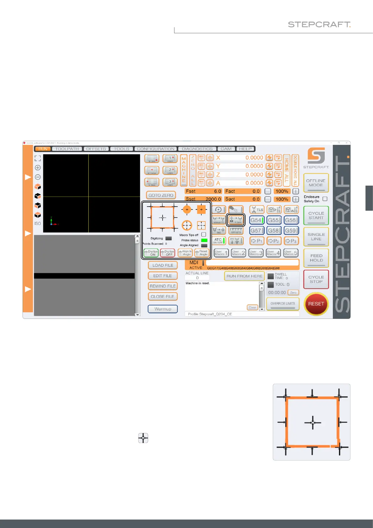
The user interface of UCCNC (depending on the used version) offers various buttons for functions using the 3D probe.
Numerous macros (previously dened workows) are integrated in UCCNC for this purpose. For example, coordinates of
edges, corners and center points can be determined automatically. You can adapt the internal coordinate system to slant-
ed workpiece edges and determine zero points that are inaccessible to end mills. You can automatically compensate an
uneven surface, which then translates into your nc-program. Furthermore, point clouds can be created in ne resolution
in order to "scan" three-dimensional objects and use them as models on the computer with third-party software.
6 Operation with UCCNC
The machine moves in the direction shown until the touch probe meets the edge.
Click one of the arrows to trigger a measurement. The representation of the black
arrow shows how the probe will move. The probe must be positioned accordingly
before triggering the measurement.
You can determine the Z-zero point with . The Z-axis is moved downwards
until the 3D probe is triggered by the surface area. The Z-value will be displayed.
6.1 Automatically Probing Contours
The touch probe can be used to automatically determine edges and corners of workpieces in various ways. The various
functions are shown below. Use these functions before using Align Angle as described in „6.4 Rotation of the Coordinate
System (Align to Angle)“.