52
EN
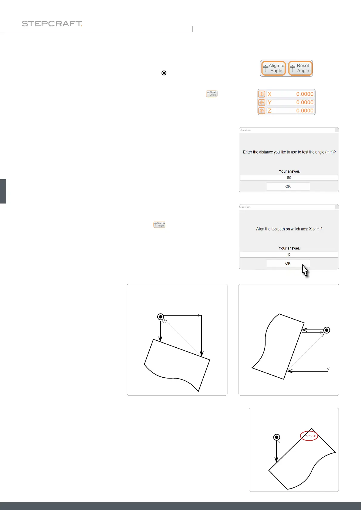
6.4 Rotation of the Coordinate System (Align to Angle)
With this function, the internal coordinate system can be adapted to diagonal-
ly clamped workpieces with the aid of the 3D probe ( ). For this purpose, two
measuring points are recorded in order to calculate the angle of the rotation.
The distance between these two points can be entered after clicking . To
realize this function, the G68 code is used. Then UCCNC will automatically
compensate all commands by the determined angle. The functions explained
in „6.1 Automatically Probing Contours“ must be used before the coordinate
system is rotated. Take note of the respective machine coordinates.
Be sure to set the zero point for X, Y and Z at the spot you want to start the
process. After measuring the needed alignment, the probe will be returned to
this position.
The slope of the workpiece is either along the Y- or X-axis. Position the 3D
probe in front of the rst measuring point so that the 3D probe can move with-
out collision after the rst measurement. Click and enter the desired
distance between measurements. Conrm and enter "X" or "Y" in the next win-
dow – depending on which axis you want to measure.
The angle is now determined ac-
cording to the illustrations to the
right. At the end of the process, the
3D probe is moved back to the start
position.
After that the angle of the work-
piece is known and the coordinate
system is rotated by this angle.
CAUTION!
If the 3D probe does not have the possibility to move the entered distance
after the rst measurement, there is a risk that it will be damaged. In this
case, either try to approach the angle from another side or align the work-
piece differently.
1.
3.
2.
50 mm
Start point touch probe
COLLISION
!
1.
3.
4.5.2.
50 mm
Start point touch probe
Movement along the X-axis.
Start point touch probe
1.
3.
4.
5.
2.
50 mm
Movement along the Y-axis.