45
EN
The 3D touch probe is used as passive tool. This tool is not actively
controlled but controlled via the X- / Y- and Z-axis of the CNC ma-
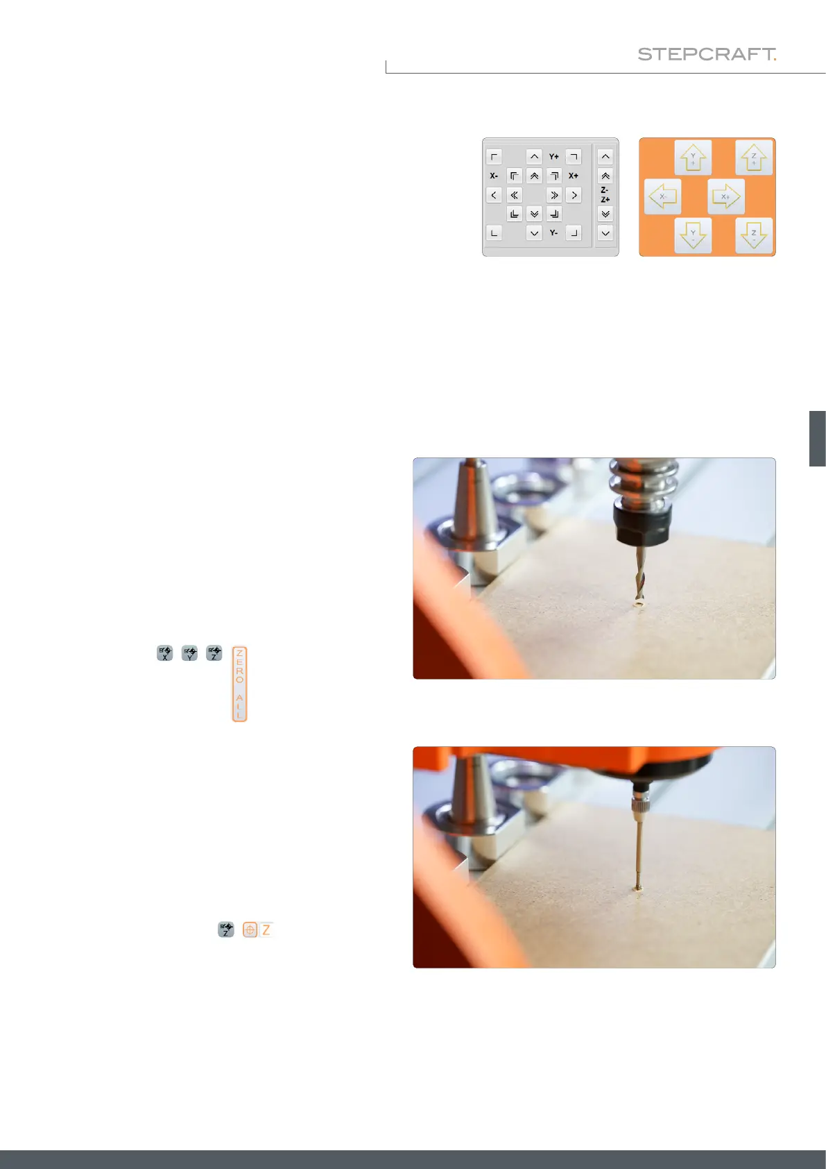
chine. Usually the touch probe is controlled manually using the CNC
software (see pictures to the right) or by use of macros (previously
saved workows).
5.4 Centering the Touch Probe Tip
In order for the 3D probe to produce reliable measured values, it is necessary to center the probe tip as accurately as
possible, in other words to align it precisely. The further the probe tip is off center between the X- / and Y-axis, the less
accurate results will be produced. There are three calibration screws on the housing, which can be used to center the
probe tip. You will need a 1.5 mm hex key. Proceed as follows:
Place a spoil board on your machine table and make
sure that it cannot move. Open your CNC software. In-
sert a milling motor (disconnected from the power sup-
ply!) holding a 2 mm end mill.
Manually traverse over the material and then descend
the Z-axis until the end mill's tip leaves a round mark.
Take note of the machine coordinates and set all work-
piece zero points
, , , .
WinPC-NC UCCNC
5.3 Control of the 3D Touch Probe
Move the Z-axis upward. Now remove the milling motor
and clamp the 3D touch probe. Make sure that the cable
points to the gap of the 43 mm euro neck for orientation
purposes. Now move the 3D probe downward until the
probe tip is directly above the 2 mm mark left earlier.
Evaluate whether the probe tip is exactly centered. Set
the Z workpiece zero point , .