43
EN
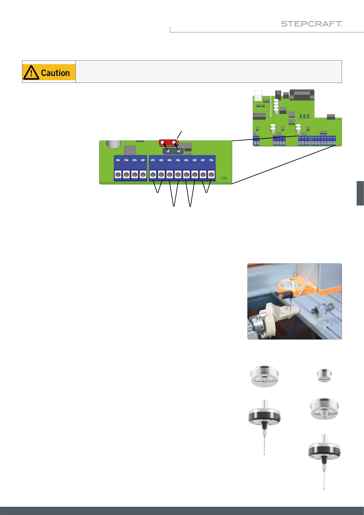
Internal Connection to the D-Series (D2)
Emergency off
WZL jumper
WZL / 3D-Probe End switch X,Y
End switch Z
The touch probe cable must be mounted in the correct position on the mainboard of your milling machine.
Using the wrong terminal can cause errors on the mainboard.
On the D-Series controller circuit board, you can x the two wires of the touch
probe directly to the terminals for the tool length sensor (WZL). Note that for
correct function, the red jumper labeled WZL must be removed.
4.3 Connection of the 3D Touch Probe
4.3.1 Using the 43 mm Euro Neck
4.3.2 Using Adapters
The housing of the 3D touch probe can be tted into a 43 mm euro neck. Be
cautious to clamp the touch probe in a straight manner.
You can use adapters in order to clamp the touch probe by use of the 8 mm
spigot. STEPCRAFT offers following options:
• Item 12369 Adapter Ø 43 mm to Ø 8 mm
• Item 10038 Adapter Ø 43 mm to Ø 20 mm +
• Item 10035 Adapter Ø 20 mm to Ø 8 mm
+
+
+