46
EN
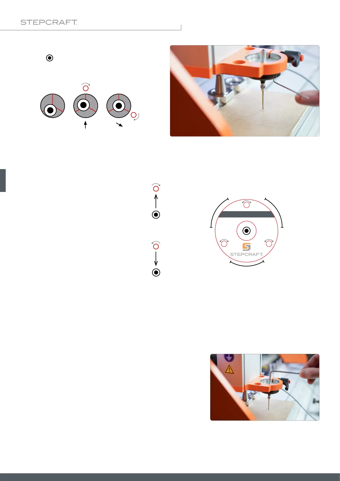
If you notice a deviation between the centers of the
probe tip ( ) and the scratch mark, move the 3D probe
up 2 mm. Use a 1.5 mm hex wrench to carefully turn
the calibration screws to counteract the deviation.
Try to only perform small changes. In between, move to the Z workpiece zero point and reassess the position of the probe
tip. Repeat this process until the probe tip is exactly centered.
Turning a calibration screw clockwise
moves the probe tip toward the calibra-
tion screw.
Turning a calibration screw counter clock-
wise moves the probe tip away from the
calibration screw.
Move one screw at a time to center the probe tip.
After the probe tip is centered, you should rotate the entire 3D probe clockwise, e. g. 90°, and check that the tip remains
centered. Repeat all steps until the probe tip is centered satisfactorily from every angle. This process takes its time, but
results in reliable measurements being obtained. Keep in mind that this procedure may be required again if you change
the method of clamping. The centering is only reliable as long as the operating conditions remain the same. For example,
if you change the xture or machine, you should check that the alignment of the 3D probe is still correct.
The sensitivity of the return spring can be adjusted with the preload
adjuster. The screw can be adjusted with a 3 mm hex key. When prob-
ing soft materials, you should set the sensitivity quite high. Otherwise,
there is a possibility that the probe tip will deform the material before it
actually triggers.
set 0 set 0
set 0
1
2
0
°
1
2
0
°
1
2
0
°
3D-Touch Probe