176
OMAHA STANDARD
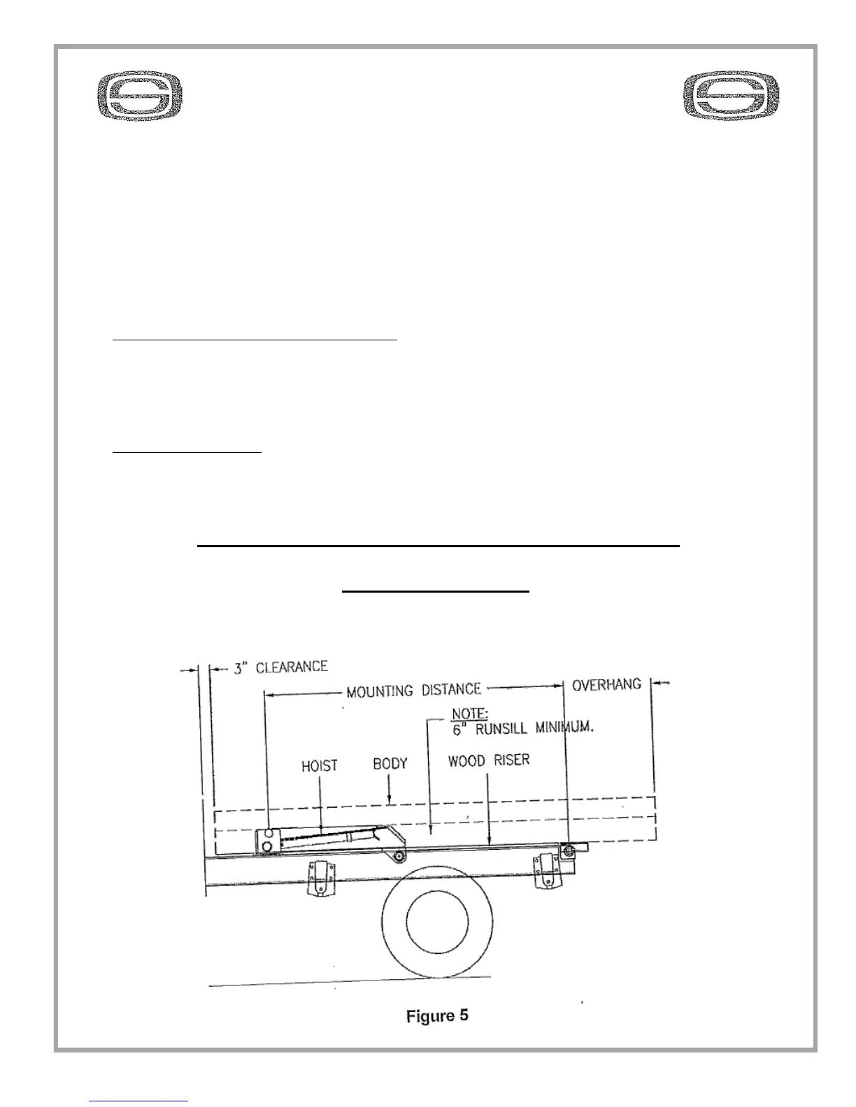
1. Plan installation of hoist by reviewing the hoist mounting diagrams (Figure 5-6) and
capacity charts in the hoist reference information section of this manual (tables 4-9)
From these determine:
A. Desire dump angle and capacity.
B. Mounting distance (centerline of hoist upper cross shaft to centerline of rear hinge
pivot point) the mounting distance for each dump angle is in the bottom row of tables 4-9
NOTE: Lift capacity ratings are based on the mounting distance. The hoist can be
reverse mounted to clear obstructions with only a slight reduction in hoist capacity.
C. POSITION HOIST ON FRAME:
1. After determining desired mounting distance, mark position of lower hoist
mounts and rear hinge on frame rails.
2. Set hoist in position on frame. It may be necessary to move hoist forward or
backward to avoid obstructions. This changes dump angle and hoist capacity.
D. VERIFY PLAN
Once you have hoist positioned on frame and have thoroughly checked for any
interference, re-check dump angle and mounting distance to verify lifting capacity.
DTH TRAILER HOIST MOUNTING DIAGRAM
STANDARD MOUNT