21
Diesel Burner Adjustments
1. Bleed all air from fuel system through bleeder screw.
See Fig. 4 (burner motor must be running).
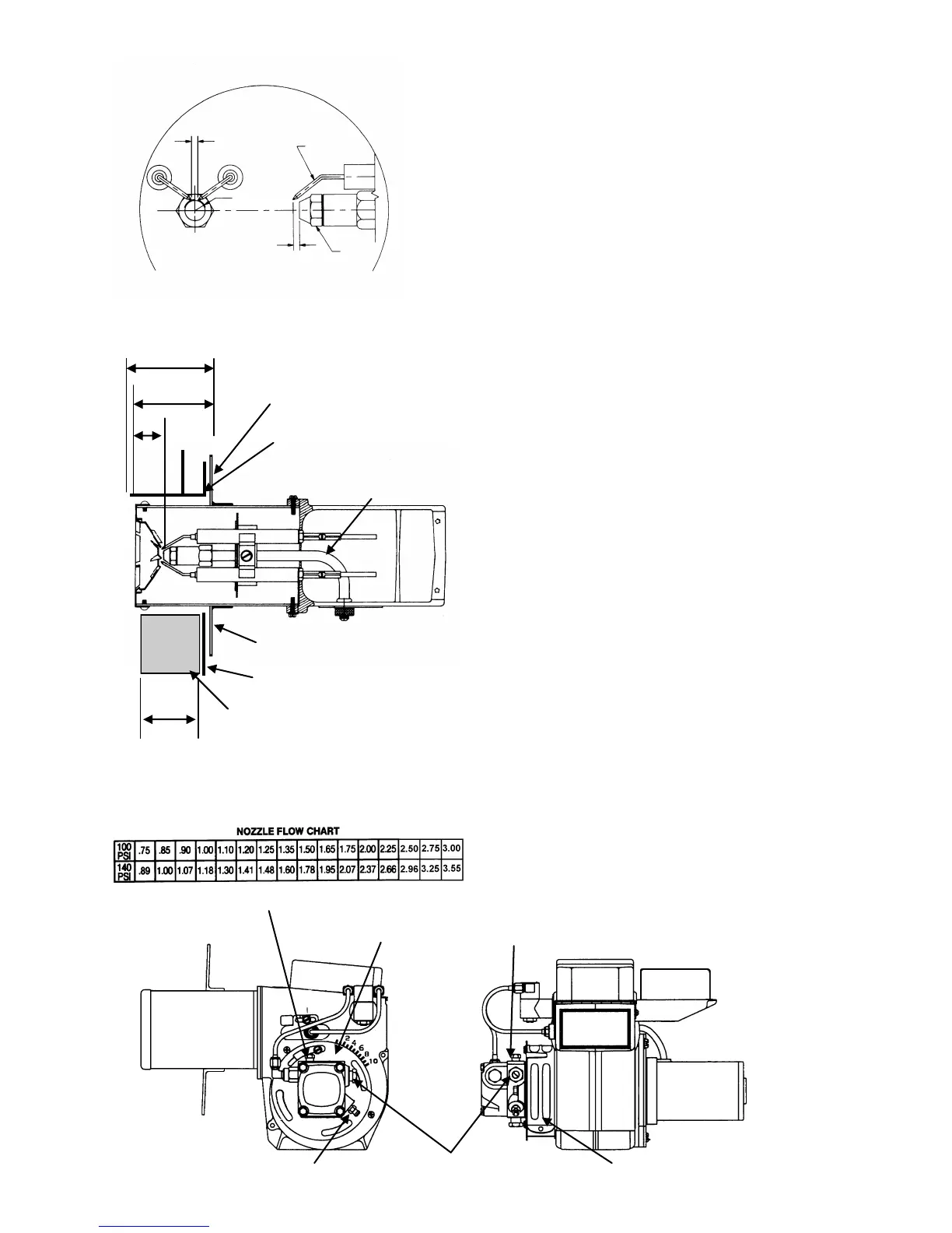
2. Check and adjust igniter electrodes as shown in Fig. 1.
3. Verify dimensional adjustments. The “Z” in dimen-
sion is set to 1 1/8’ by repositioning the nozzle line.
The “A” dimension is set 1/4” less than the “C” di-
mension by repositioning the mounting flange. Refer
to the mounting methods shown in Fig. 2.
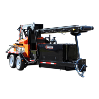
4. Check and adjust fuel pressure to 140 psi. 100 psi
minimum may be used to compensate for high altitude
operations (refer to Fig. 3).
5. Set initial adjustment of air band and air shutter to
number six. Ignite the burner and adjust the air supply
until there is a slight amount of smoke. See Fig. 4.
6. Allow temperature to rise to at least 150º F. then read-
just air supply until there is just a trace of smoke.
7. Using combustion analyzer, measure the CO
2
or O
2
levels. Then increase the air supply to reduce the CO
2
by 1%, or increase the O
2
by 1%. If an analyzer is
not available, increase the air supply until the smoke
just disappears.
8. Tighten all screws after final adjustments are made.
Electrode Adjustment - Fig.1
5/32”
electrode
5/32”
nozzle
“C”
“A”
“Z”
Mounting Flange
Burner Mount Tube
(mounting method 1)
Nozzle Line
Mounting Flange
Combustion Chamber Wall
(mounting method 2)
Insulation (mounting method 2)
“C”
Dimensional Adjustments - Fig. 2
Fig. 3
Fig. 4
Pressure Port
Air Shutter
Pressure Port
Pressure Regulator Bleeder Screw Air Band