WORKSHOP MANUAL
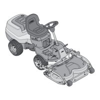
Map of functional units
MP 84/98 - MP 84/98 Hy
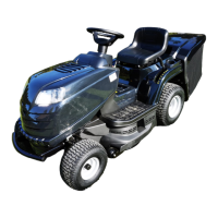
provide (and consequently determine the “neutral”
position for the pedal), it is necessary that the inner
lever (3) on the pedal axis is located perfectly vertical
with the lever (2) of the hydrostatic unit in “neutral”.
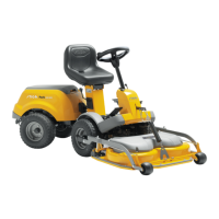
This is obtained using a bracket (4), by working on
the nuts (5) until reaching the desired situation, tak-
ing care not to accidentally change the position of the
lever (3) during adjustment.
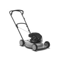
When adjustment has been completed, move the pe-
dal (6) to the reverse position and check that the lo wer
section (6a) touches the footboard.
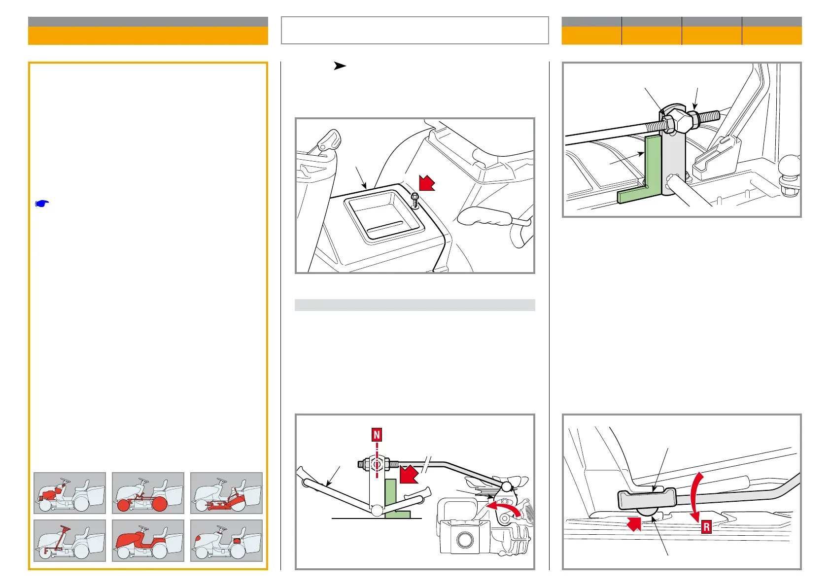
hydrostatic drive models only
All the adjustment elements can be accessed by re-
mo ving the inspection hatch (1).
A) Adjusting the pedal in the “neutral” position
Regulating consists of adjusting the position of the
pedal (3) with the hydrostatic group lever (2), which
is brought to the forward maximum speed position by
a spring.
To get the speeds that both forward and reverse gears
General informations
This operation should be carried out every time
the rear axle, pedal or control rod is removed, in
order to get the correct travel for the pedal and to
reach the envisaged speeds both forwards and
in reverse.
Related topics
[
7.10] Fitting safety microswitches
DRIVE PEDAL ADJUSTMENT
CHAPTER REVISION FROM ... PAGE
4.4 0 2018 1 of 2
3
2
4
5 5
1
6
6a