WORKSHOP MANUAL
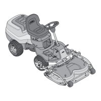
Map of functional units
MP 84/98 - MP 84/98 Hy
Remove the left and right side guards (if provided).
Check the tyre pressures. If one or more tyres have
been replaced or you nd dierences in diameter, do
not attempt to compensate these dierences by
giving dierent tyre pressures, but make the ad-
justments as in points «A» and «B».
A) Combined adjustment to the parallel and
the minimum front and rear height
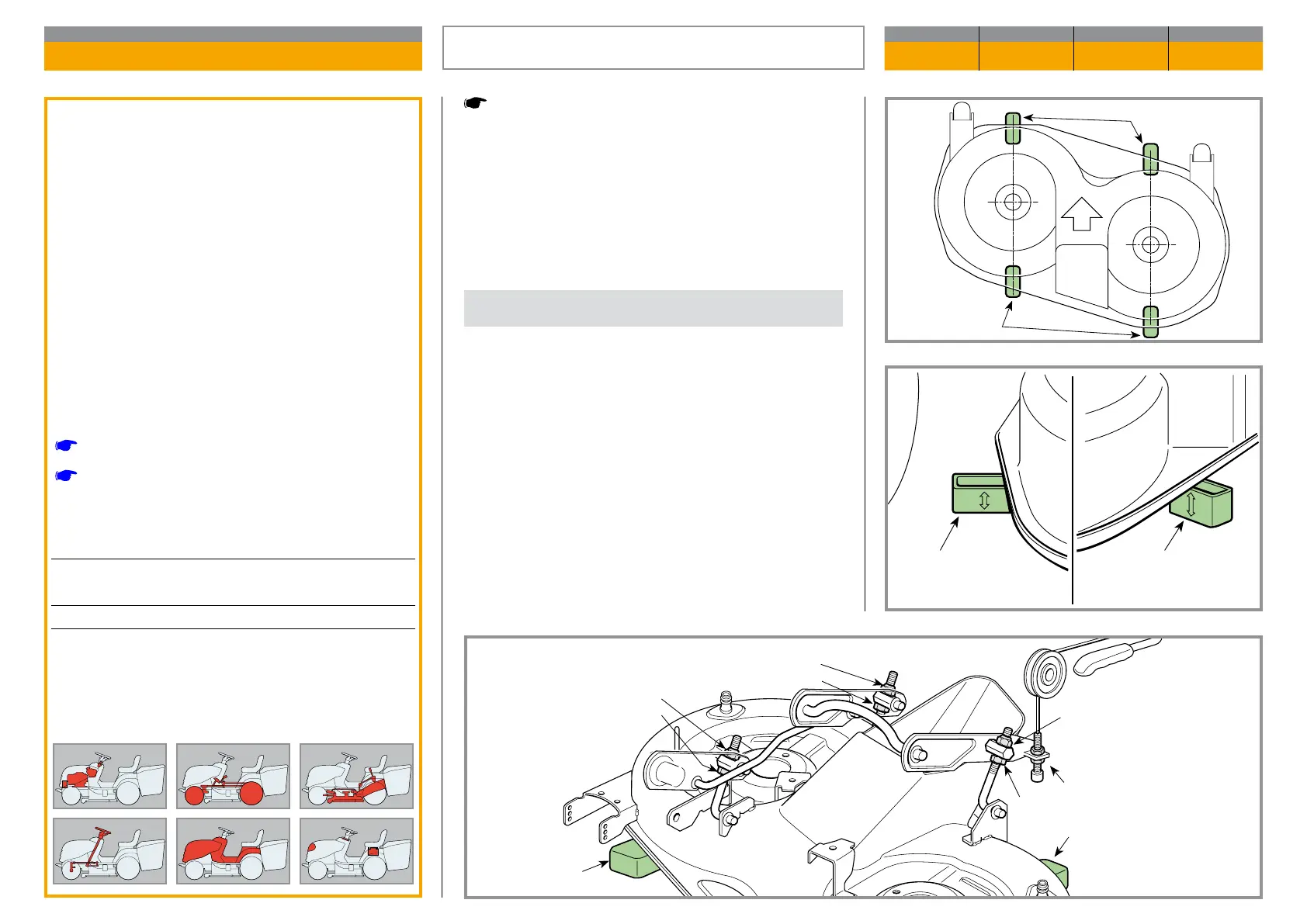
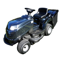
Put the lawn-tractor onto a at and stable surface
(such as a work bench) and put blocks beneath the
cutting deck in line with the centre lines of the blades:
– at the front 26 mm (1)
– at the rear 32 mm (2)
Put the height lever in position «1».
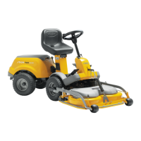
Completely loosen the adjuster (3), the nuts (4 - 6 - 8)
and the locknuts (5 - 7 - 9) of the three trace rods until
the deck is resting on the blocks.
General informations
The cutting deck is lowered by a level controlled
ca ble, and is moved by two trace rods at the front
and back.
In order to get a good cut it is essential that the
cut ting deck is parallel with the ground crosswise,
and slightly lower at the front.
Two adjustments can be made on the jointed sy
s tem of the cutting deck:
a) a combined adjustment to the parallel and the
minimum height front and back
b) an adjustment to just the parallel across the
cutting deck
Related topics
[
2.2] Tools
[
5.2] Removal of the side guards (if provided)
Tightening torques
Front ......................... (Tyres 13 x 5.00-6) 1,5 Bar
.................................... (Tyres 15 x 5.00-6) 1,0 Bar
Rear .......................................................... 1,2 Bar
ALIGNING THE CUTTING DECK
CHAPTER REVISION FROM ... PAGE
4.5 2 2018 1 of 2
1 2
- h = 26 mm
- h = 32 mm