WORKSHOP MANUAL
Map of functional units
MP 84/98 - MP 84/98 Hy
IMPORTANT When assembling, ensure fas
teners are used, being essential to allow disassembly
and reassembly of the guards by user, without jeop
ardizing the safety of the machine.
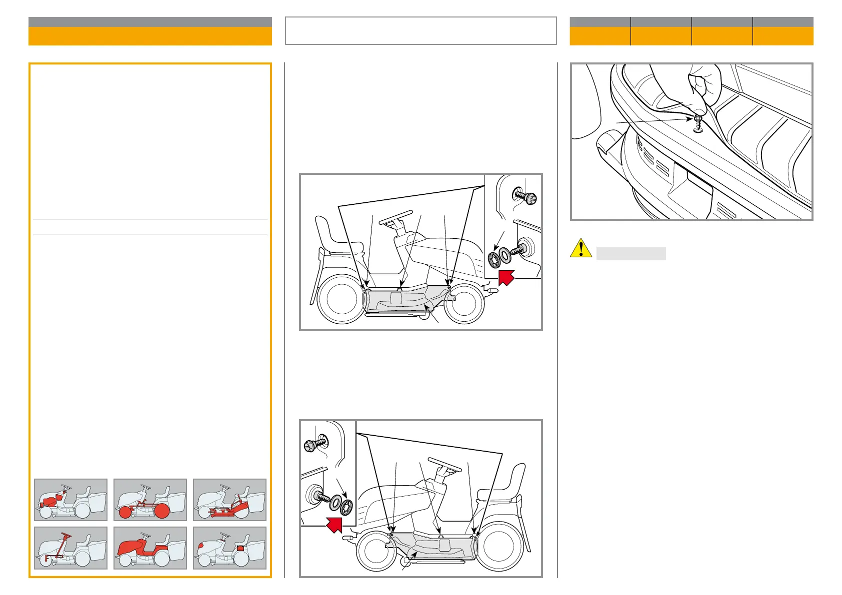
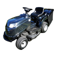
Each guard (1 - right) or (2 - left) is fastened by:
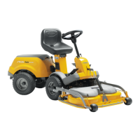
– 1 top self-tapping screw (3),
– 1 front self-tapping screw (4),
– 1 rear self-tapping screw (5),
The front self-tapping screws (4) and rear (5) are held
with a ring gear fastener (6) that keeps them inserted
in the respective seats.
General informations:
The removal of side guards allows access to the
blades drive belt and cutting deck adjusting keys.
Related topics:
---
Tightening torques
3 - 4 - 5 Guards fastening screws ....... 8 ÷ 10 Nm
REMOVAL OF THE SIDE GUARDS
(if provided)
CHAPTER REVISION FROM ... PAGE
5.2 0 2018 1 of 1
2
34 5
6
3